
Product data

7800 SERIES S7800A1142 KEYBOARD DISPLAY MODULE
5 65-0288-1
4. For Recommended grounding practices, see Table 2.
5. For KDM: The KDM is powered from a low voltage,
energy-limited source. It can be mounted outside of a
control panel if it is protected from mechanical damage.
NOTE: A 13 Vdc power supply must be used any time more
than one KDM is used. A maximum of two KDM, Data
ControlBus™ Modules or S7810B Multi-Drop Switch
Modules are allowed in any combination.
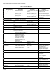
Table 1. Recommended Wire Size and Part Number.
Table 2. Recommended Grounding Practices.
6. Recommended wire routing:
a. ControlBus:
(1) Do not route the ControlBus cable in conduits
that carry line voltage circuits.
(2) Avoid routing the ControlBus cable close to
ignition transformer leadwires.
(3) Route the ControlBus cable outside of conduit if
properly supported and protected from damage.
b. Remote Reset:
(1) Do not run high voltage ignition transformer wires
in the same conduit with the Remote Reset wir-
ing.
(2) Do not route Remote Reset wires in conduit with
line voltage circuits.
7. Maximum wire lengths:
a. KDM: The maximum length interconnecting wire is
4000 ft (1219m).
b. Remote Reset leadwires: The maximum length wire
is 1000 ft (300m) to a Remote Reset push-button.
8. Install all electrical connectors.
9. Restore power to the panel.
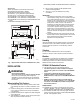
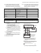
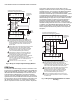
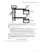
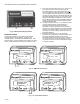
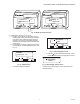
Fig. 5. Wiring the Keyboard Display Module.
Application Recommended Wire Size Recommended Part Number
Keyboard Display Module 22 AWG two-wire twisted pair with
ground, or five-wire.
Belden 8723 shielded cable or equivalent.
Data ControlBus™ Module 22 AWG two-wire twisted pair with
ground, or five-wire.
Belden 8723 shielded cable or equivalent.
Remote Reset Module 22 AWG two-wire twisted pair, insulated
for low voltage.
—
Communications Interface ControlBus
Module™
22 AWG two-wire twisted pair with
ground.
Belden 8723 shielded cable or equivalent.
13 Vdc full wave rectified transformer
power input.
18 AWG wire, insulated for voltages and
temperatures for given applications.
TTW60C, THW75C, THHN90C
Ground Type Recommended Practice
Signal ground (KDM, Data ControlBus™
Module, Communications Interface
ControlBus Module™).
Use the shield of the signal wire to ground the device to the signal ground terminals
[3(c)] of each device. Connect the shield at both ends of the daisy chain to ground.
1
1
1
A
B
A
B
C
1
23
4
5
1
23
2
2
3
3
S7800 KEYBOARD DISPLAY MODULE
(MOUNTED ON 7800 SERIES RELAY MODULE)
C (GND)
+13 VDC
RESET
MOMENTARY
PUSH BUTTON
SWITCH
120 OHM
RESISTOR
120 OHM
RESISTOR
QS7800 COMMUNICATIONS
INTERFACE CONTROLBUS
MODULE, MOUNTED IN
Q7700 COMMUNICATIONS
INTERFACE MODULE
THREE-WIRE SHIELDED CABLE MAY BE REQUIRED. TWO 120
OHM TERMINATING RESISTORS ARE REQUIRED FOR
CONNECTIONS OVER 100 FEET (30 METERS). CABLE SHIELD
MUST BE TERMINATED TO EARTH GROUND AT BOTH ENDS.
IF SHIELDED CABLE IS NOT USED, TWISTED PAIR WIRE
MUST BE USED.
WHEN CONNECTING THE KEYBOARD DISPLAY MODULE, DATA
CONTROLBUS MODULE, OR REMOTE RESET MODULE EXTERNAL
FROM THE CONTROL CABINET, APPROPRIATE MEASURES MUST
BE TAKE TO MEET EN60730 SAFETY LOW VOLTAGE
REQUIREMENTS (SEE APPROVALS).
TERMINALS OF 203541 5-WIRE CONNECTOR.
M1990G