AW58300HTP-PAIR USER’S MANUAL 5.
AW58300HTP-PAIR User’s Manual The AW58300HTP-PAIR consists of two AW58300HTS radios preconfigured with a dual flat panel high gain directional antenna. The AW58300HTP-PAIR includes: (2) AW58300HTS Bridge Radios (2) Heavy Duty Pole-mount Bracket (2) Power Over Ethernet Injector (2) 18 VDC Power Supplies Table of Contents Quick Start Guide . . . . . . . . . . . . . . . . . . . . . . . . . . . . . . . . . . . LED Status Guide . . . . . . . . . . . . . . . . . . . . . . . . . . . . . . . . . . .
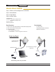
AW58300HTP-PAIR User’s Manual Quick Start Guide Step 1. Radios are Preconfigured out of the Box Step 2. Mount Radios Step 3. Align Radios Step 4. Attach Cables System Default: IP Address: 192.168.88.12 (Bridge A Unit) 192.168.88.10 (Bridge B Unit) Username: admin Password: password Tools Needed: Best Practices: 1. Ensure clear visual path between radios before deployment - ½ inch wrench 2. Test on bench before deployment - Large Phillips head screwdriver 3.
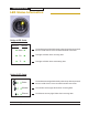
AW58300HTP-PAIR User’s Manual LED Status Information Bridge A LED Guide Ethernet Wireless Status The wireless status light blinks slowly when the product is powered and is lit solid when it has a successful wireless connection. Rx This light will blink when receiving data Tx This light will blink when transmitting data Bridge B LED Guide Status The wireless status light blinks slowly when the product is powered and is lit solid when it has a successful wireless connection.
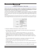
AW58300HTP-PAIR User’s Manual Digital Configuration Connecting to the radio 1. Digital configuration is done by means of the radio’s built in browser interface. The unit should be powered on and connected at least temporarily to a network containing a computer that can run a conventional web browser. 2. Using your web browser, connect to the radio as described in the Quick Start Guide found earlier in this manual. 3. The initial page after a successful login is “Quick Set.
AW58300HTP-PAIR User’s Manual Changing The Configuration - Step by Step Please be aware that if you change the IP Address or User Password and forget their new values, you have locked yourself out of the browser interface. The AW58300 runs self-diagnostics at boot-up and will auto-correct most system configuration errors. Prior to calling technical support, it is recommended to power cycle the radio and confirm that the problem remains.
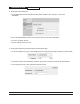
AW58300HTP-PAIR User’s Manual 2. Setting the User Password: • On the Main Menu at the left side of the browser window, click “System”, then click “Password.” • Enter the old password and the new password twice in the boxes indicated. • Click the “Change” button. • Log out and log back in to test. 3. Setting the Frequency, Network name and Encryption Key: • To set the Frequency, log in to the Bridge A and on the quick start page a selection can be made.
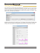
AW58300HTP-PAIR User’s Manual Viewing Status Information After configuring your AvaLAN radios and establishing links among them, you can use the browser interface to view status and troubleshooting Information. The initial “Quick Set” page will show whether the wireless link is operating and the current signal strength. For more comprehensive information, choose “Wireless” from the Main Menu at the left side of the window. The “Wireless” page leads to most of the useful status information.
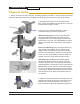
AW58300HTP-PAIR User’s Manual Physical Setup 1. Mount each unit securely using the mounting brackets provided or other means as necessary. Maximize lightning resistance by providing a strong DC ground connection to the metal housing. A. Assemble both bracket arms using the Rotator Bolt, a Large Lock Washer and the Hex Nut. Leave the bracket loose enough to rotate. B. Use one of the following methods, or other methods necessary to seccure the bracket.
AW58300HTP-PAIR User’s Manual D. Use a large Phillips head screwdriver to mount your radio to Bracket Arm B using the four Radio Mounting Screws. Use small washers and lock washers if necessary. Make sure that the orientation arrow on the back of the panel antenna faces upward so that the drainage hole is at the bottom of the radio. E. Assemble the cable gland on the end of your RJ45 Ethernet cable(not provided). Then connect the cable to your radio’s Ethernet port, and fasten the gland.
AW58300HTP-PAIR User’s Manual A. Connect the opposite end of your Ethernet cable to the Power over Ethernet Injector, and the RJ45 tail of the PoE to your network. B. Connect the PoE to your 18 VDC Power Supply and it to a standard 120 VAC outlet.
AW58300HTP-PAIR User’s Manual Technical specifications CHARACTERISTIC SPECIFICATION/DESCRIPTION RF transmission rate 300 Mbps Ethernet data rate Up to 180 Mbps Output power AW58300HTP 200 watts EIRP with 23 dBi directional antenna Receiver Sensitivity -115 dBm Frequency Range 5.150 - 5.250 and 5.725 - 5.
AW58300HTP-PAIR User’s Manual Frequency Channels Frequency MHz *Auto - auto scans for unused requency 5180 5220 5745 5805 Limited Warranty This product is warranted to the original purchaser for normal use for a period of 360 days from the date of purchase. If a defect covered under this warranty occurs, AvaLAN will repair or replace the defective part, at its option, at no cost. This warranty does not cover defects resulting from misuse or modification of the product.