• Masonry Fireplace • Factory Built (Metal) Fireplace • Mobile Home Approved Tested and Listed by Omni-Test Laboratories, Inc. Portland, Oregon Report # 028–S–51-2 ASTME-1509 1995, ULCC 1482 Astoria Bay™ Pellet Insert - - Please read this entire manual before installation and use of this pellet fuel-burning room heater. Failure to follow these instructions could result in property damage bodily injury or even death.
Introduction 2 Introduction We welcome you as a new owner of a Astoria Bay pellet heater. In purchasing a Astoria Bay you have joined the growing ranks of concerned individuals whose selection of an energy system reflects both a concern for the environment and aesthetics. The Astoria Bay is one of the finest home heaters the world over. This manual will explain the installation, operation, and maintenance of this pellet-burning heater.
Table of Contents Introduction 3 Operation (continued) Introduction ......................................................2 Important Information .........................................2 Manual Mode.....................................................19 Auto Mode ........................................................20 Restrictor Adjustment .........................................21 Adjusting the Fan Speed......................................21 Start-Up Sequence....................................
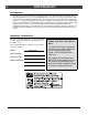
Safety Precautions 4 • Do not operate the heater if you smell smoke coming from the heater. Turn the P OWER switch to "OFF", monitor your heater, and call your dealer. Gas Ok • Never use gasoline, gasoline-type lantern fuel, kerosene, charcoal lighter fluid, or similar liquids to start or 'freshen up' a fire in this heater. Keep all such liquids well away from the heater while it is in use. Se • Never try to repair or replace any part of the heater unless instructions are given in this manual.
Safety Precautions ? • The heater will not operate during a power outage. If a power outage does occur, check the heater for smoke spillage and open a window if any smoke spills into the room. • This heater must be connected to a standard 115 V., 60 Hz grounded electrical outlet. Do not use an adapter plug or sever the grounding plug. Do not route the electrical cord underneath, in front of, or over the heater. • Keep foreign objects out of the hopper.
Specifications 6 Heating Specifications: Approximate Maximum Heating Capacity (in square feet)* ........................................800 to 2,250 Burn Rate (Pounds per Hour)**............................................................................1.7 to 5.5 Maximum Burn Time on Low Burn** ......................................................................28 to 52 Hours Hopper Capacity (based upon hopper extension position).........................................
Installation 7 Before You Begin READ THIS ENTIRE MANUAL BEFORE YOU INSTALL AND USE THIS HEATER. FAILURE TO FOLLOW THE INSTRUCTIONS MAY RESULT IN PROPERTY DAMAGE, BODILY INJURY, OR EVEN DEATH. Check with local building officials for any permits required for installation of this pellet heater and notify your insurance company before proceeding with installation.
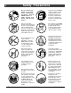
Installation 8 Hopper Extension Set-up This pellet heater has a variable-height hopper. This allows the hopper to be lowered for smaller fireplaces. Follow the instructions below to set the correct hopper extension position. • Determine the correct hopper extension position following the directions below. The unit will extend 14” into the fireplace. For setting the hopper, the maximum fireplace opening measurements have to be taken at 14” into the fireplace.
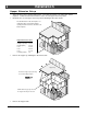
Installation • 9 Remove the correct knock-outs in the hopper walls following the directions below. If you are using hopper extension position F, remove the top knock-out. If using position E, remove the second knock-out, (etc...). The second-to-bottom knock-out is position B. Position F Knock-Out Position E Knock-Out Use a center-punch (or other suitable tool) to remove the appropriate knock- Position D Knock-Out outs in the hopper walls (punch the holes out from the inside).
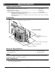
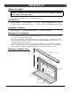
Installation 10 Clearances • Insert must be placed so that no combustibles are within, or can swing within (e.g. drapes, doors), 36" of the front of the heater. • Insert must be placed a minimum 8-3/4" from a side wall (or combustible protruding more than 3/4"). AAA AA AAA AA AAA AA AAAAA AAA AA AAA AA AAAAA AA AAAA AAAAAAA AAAA AAAA AAAA AA AA AA AA AA AA AA AA AA AA AA AA AA AA AAAAAAAAAAAA AA 12” The mantel must fall within this shaded area (or above).
Installation 11 Venting the Pellet Stove • INSTALL VENT AT CLEARANCES SPECIFIED BY THE VENT MANUFACTURER). • DO NOT CONNECT THE PELLET VENT TO A VENT SERVING ANY OTHER APPLIANCE OR STOVE. • DO NOT INSTALL A FLUE DAMPER IN THE EXHAUST VENTING SYSTEM OF THIS UNIT. • USE AN APPROVED WALL THIMBLE WHEN PASSING THE VENT THROUGH WALLS AND A CEILING SUPPORT/FIRE STOP SPACER WHEN PASSING THE VENT THROUGH CEILINGS (MAKE SURE TO MAINTAIN CLEARANCE TO ANY COMBUSTIBLES.
Installation 12 Mobile Home Requirements • Outside air is required (used for combustion) - see the directions below. WARNING: DO NOT INSTALL IN SLEEPING ROOM. CAUTION: THE STRUCTURAL INTEGRITY OF THE MANUFACTURED HOME FLOOR, WALL, AND CEILING/ROOF MUST BE MAINTAINED. Outside Air (used for combustion) • Outside air is optional (except in mobile homes or when required by local building codes). • Must not be drawn from an enclosed space (garage, unventilated crawl space).
Installation 13 Baffle Installation Install the baffles included with the insert (see page 28 for details). Restrictor Adjustment The restrictor is used to adjust airflow to the firepot. It should be adjusted to match the heat output setting and burn the pellets at the appropriate rate. This keeps the firepot as clean as possible. For low heat output settings the restrictor will need to be closed or near closed to limit the amount of air.
Installation 14 Surround Panel & Circuit Board Installation NOTE: Attach the vent prior to installing the surround panels (& circuit board). a Attach the surround panels to the insert by sliding the slots e on each panel over the tabs on the side of the insert. Slot NOTE: When in place, the panels maintain a 3/8” gap around the fireplace. Tab Phillips Screwdriver Remove the circuit board from the rear hopper support.
Installation 15 Installation into a Masonry Fireplace Vertical Cap “L” Vent Cover Plate (non-combustible) AAAAA AAAA AAAAA AAAA AAAA AA AAA AA AAAA AA AA AAAA AAAA AA AAA AA AAAAAA AAA AAAAAA AA AAAA AA AA AAA AA AAAA AA AAA AA AAAAAA AAAA AA AAA AA AA AA AA AAA AA AA AA AAAA AA AAA AAAA AA AA AAA AA AA AA AAAA AA AAA AA AA AAAA AA AAAA AA AA AA AAAAA AA AA AAAA AA AAAA AAAAA AA AA AA AAA AA AAAAA AA AA AAAA AAA AAAAA AA AA AAA AA AAAA AAAA AAAAA AA AAA AA AAA AAAA AAAA AAA AAAAA AA AAA AA AA AAAA AAAA
Installation 16 Installation into a Factory Built (Metal) Fireplace Vertical Cap “L” Vent Cover Plate (non-combustible) AA A AA A AA A AA A AAA AAA AA A AA A AAA AAA AA A AA A AA A AA A A AA A AA A A AAAAA AA A AA A A AAAA AA AAAAA AAA AAA AAAAA AA AAAAA AA A AA A A AAAA AAAAAA AA AAAAA AAAAAAAAAA AA AA A AA A A AA AA A AAAA AA A A AAAAAA AAAAA AA A A AAAAAA AA AA AA AAAA A AA AA A AA A A AAAAAA AA AAAAAAA AA A A AA AAAAAA A AA AAAA AA AA A AAA AA A A AAAAAA A AA A AA AAAAAAAA AAAAAA AAAAA AAA AA A A A
Operation 17 Safety Notice • Read this entire manual (especially the "Safety Precautions" on pages 4 and 5) before using this heater. Failure to follow the instructions may result in property damage, bodily injury, or even death. • Do not unplug the heater to turn it off. This heater relies upon electricity to push the flue gases out the pellet vent – unplugging it may lead to smoke entering your room.
Operation 18 Loading Pellets Lift the hopper lid to its vertical position. Pour pellets into the hopper until full. NOTE: The hopper holds approximately 48 to 88 pounds of pellets (depending upon hopper set-up). The front edge of the hopper lid becomes very hot, do not touch the area below the handle. AA AA s e t l l Pe AAAAAAA AAAA AAAAAAA AAAAAA AAAAA AAAAA AAAA AA AAAAAAA AAAAAA AAAAA AAAAA AAAA AAAA AA AAAAAAA AAAAAA AAAAA AAAAA AAAA Make sure pellets are not left on this heat shield.
Operation 19 Manual Mode Manual mode requires the user to turn the heater on and off manually. H E A T To Start Press the "Manual Start" button. That's it. The stove automatically goes to a medium burn rate and high fan while the igniter starts the fire burning within 10 minutes. During this period the lowest “HEAT OUTPUT” light will flash. If the stove does not start in 30 minutes, the stove turns off.
Operation 20 Auto Mode Auto mode allows you to use a thermostat to control room temperature. The stove automatically turns on when the temperature drops below the thermostat setting. Once the stove reaches operating temperature, the stove then runs at the heat output setting selected. To Adjust Room Temperature (or Start the Stove) Move the thermostat to the heat setting desired. If the room is cooler than the setting, the stove will go through the start-up sequence for approximately 10 minutes.
Operation 21 Restrictor Adjustment The restrictor is used to adjust airflow to the firepot. It should be adjusted to match the heat output setting and burn the pellets at the appropriate rate. This keeps the firepot as clean as possible. For low heat output settings the restrictor will need to be closed or near closed to limit the amount of air. This prevents the stove from burning the pellet fuel faster than it is fed.
Operation 22 Start-Up Sequence This stove utilizes a start-up sequence whenever the mode switch is changed or the heater is started when cold. This is to ensure proper operation through all possible settings and operational states (hot or cold, pellets burning or not burning, etc.). This sequence over-rides all user settings (except the "OFF" position) to set the auger feed rate to medium, the exhaust blower to high, and the igniter on. During this period the lowest “HEAT OUTPUT” light will flash.
Operation 23 "MANUAL AUGER" Button This button turns the auger on. It is used to “prime” the auger after the hopper has run out of pellets. Power Outages If a sustained power outage occurs while in "Manual", the heater will go to a "cool down" mode to vacate smoke once power returns. If the power outage was short, the heater will go to the start-up sequence. If in "Auto", the heater will re-start (if the room is cool).
Maintenance 24 Daily Maintenance (whenever using the heater) Inspect the Burn When burning on high, the flames should be bright orange with embers jumping from the firepot. NOTE: the optimal restrictor position will vary over time as soot builds up inside the exhaust system. See "Restrictor Adjustment" for details. Make Sure Pellets are Not Piling Up If the pellets pile up over the burn pot, turn the mode switch to "OFF".
Maintenance 25 Daily Maintenance (whenever using the heater) - Continued Check Firepot for Clinkers If the flames seem to be coming only from the sides, or are orange/black, turn the heater off and check for clinkers.
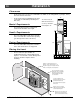
Maintenance 26 Daily Maintenance (whenever using the heater) - Continued Opening The Door Phillips Screwdriver Bracket (attached to side of heater) AAAA AAAAAAAAA AAAAAAAAA AAAAAAAAA AAAAAAAAA AAAAAAAAA AAAAAAAAA AAAAAAAA AAAA AAAAAAAA AAAA AAAAAAAA AAAAAAAA AAAAAAAA Pawl Door Frame Lock Nut With the pawl free of the bracket, Swing open this panel to access the door latch (use the tool if necessary). the door may be swung open.
Maintenance 27 Weekly Maintenance (or every 5 bags of pellets) Flyash Removal This heater was designed to allow for easy flyash removal with the included tools. However, to ease maintenance, several pellet stove owners have purchased vacuums specifically made to remove flyash. Furthermore, some of these vacuums are heat-resistant to allow for flyash removal while it is still warm. Do not use a standard vacuum on this appliance (except to clean the pellet dust out of the hopper).
Maintenance 28 Weekly Maintenance (or every 5 bags of pellets) - Continued Check Baffles, Ashbox, Ashpan, Dispose Ash If Necessary NOTE: The left baffle is larger than the right baffle. WARNING: The front of the heater becomes very hot during operation. Let the heater cool completely before conducting service. Cleaning the Baffles Use both hands to lift each baffle up and forward. Then tilt the baffle downwards to remove any flyash that may have accumulated on top of the baffle.
Maintenance 29 Weekly Maintenance (or every 5 bags of pellets) - Continued Sweep Ash Into Ashpan HINT: The more often you clean out the flyash, the more efficient your heater will burn. NOTE: Remove the ashbox prior to conducting the service below. WARNING: The firebox becomes very hot during operation. Let the stove cool completely before conducting service. a Lift it up and away from the firebox. Repeat for the opposite side. b Swing the side ash trap door up.
Maintenance 30 Yearly Maintenance (or every ton) WARNING: Disconnect the power cord prior to conducting service. The following section details extensive maintenance procedures. We strongly suggest these items be carried out by a trained service technician, possibly by a service agreement set up with your dealer. Soot and Flyash: Formation and Need for Removal – The products of combustion will contain small particles of flyash.
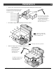
Maintenance 31 Yearly Maintenance (or every ton) - Continued Clean the Exhaust Blower (make sure the heater is cool and unplugged) a Remove the surround panels and access Remove the six screws holding the b exhaust blower motor in place. the left side of the heater. Remove the shroud covering the blower motor. 11/32" Socket c Pull the motor out (be careful not to damage the wiring or blades).
Maintenance 32 Yearly Maintenance (or every ton) - Continued Door Seal ! • Air leaks into the firebox will decrease the stove's performance greatly, leading to excessive sooting, inefficient burning, and perhaps a malfunction. The door gasket must contact the entire perimeter of the door and create an airtight seal. To verify this, open the door, hold a dollar bill against the body of the heater, close the door, and secure the latch.
Maintenance 33 Yearly Maintenance (or every ton) - Continued Adjusting the Door Hinge and Latch • The door hinge and door latches may be adjusted to pull the door closer to the body. The illustration below details how to adjust these components. NOTE: Make sure to read the section "Door Alignment" on the previous page before adjusting the door. Latch Adjustment Loosen the lock nut and twist the pawl (clockwise to tighten, counter-clockwise to loosen). Tighten the lock nut to secure in place.
Maintenance 34 Yearly Maintenance (or every ton) - Continued Check for Air Leaks Around the Door, Glass, and Ashpan ! • • • Air leaks into the firebox will decrease the stove's performance greatly, leading to excessive sooting, inefficient burning, and perhaps a malfunction. Inspect the door gasket to make sure it is fully attached. Use stove gasket cement to re-attach if necessary. If the door gasket is worn or flattened, replace. If the glass is cracked, replace.
Normal Operating Sounds 35 Auger Motor When feeding pellets, you may hear the intermittent buzz of this motor running. Exhaust Blower The blower may create a low-pitched hum. This sound will change as the FEED RATE is altered. Heat Exchanger Tubes You may hear the heated air being forced through these tubes by the convection fan. Firepot As pellets are fed into the firepot, a light clicking sound may be heard.
Safety Label WARNING - DO NOT REMOVE OR COVER THIS LABEL Model: Astoria Bay PI (Avanti PI) Electrical Rating: 115 V., 60 Hz., Report No.: 028-S-51-2 Start 3 Amps, Tested to: ASTM E1509-95 Run 1.5 Amps Maximum Input Rating: 5.5 lbs (2.50 kg)/hr This pellet appliance has been tested and listed for use in manufactured homes in accordance with Oregon Administrative Rules 814-23-900 through 814-23-909. Install and use only in accordance with the installation and operating instructions.
Limited 7 Year Warranty 37 To register your TRAVIS INDUSTRIES, INC. 7 Year Warranty, complete the enclosed warranty card and mail it within ten (10) days of the appliance purchase date to: TRAVIS INDUSTRIES, INC., 4800 Harbour Pointe Blvd. SW, Mukilteo, WA 98275. TRAVIS INDUSTRIES, INC. warrants this gas appliance (appliance is defined as the equipment manufactured by Travis Industries, Inc.
Optional Equipment 38 Thermostat (Part # 99300650) ! Do not connect 120 VAC to the thermostat circuit of this heater (do not use a household thermostat used for a wall-board or other electical heater). 1 2 Attach the thermostat wire to the circuit board (see the illustration to the right). Route the wire through the back of the heater (away from any hot or moving components). Determine a location for the thermostat that is within range of the 20' length of thermostat wire.
Optional Equipment ZC Kit 39 (99200149) The optional zc kit allows this insert to be directly into the framing of a house or mobile home. See the kit for installation details.
Index 40 Adjusting the Fan Speed......................................21 Air Leaks..........................................................32 Ashpan (Opening and Disposing Ashes) .................28 AUGER ON Light................................................22 Auto Mode ........................................................20 Blower (Exhaust Blower Cleaning) .........................31 Blower Speed Adjustment ....................................21 Cap (Pellet Vent Termination) ......................