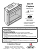
AAAAAAAAAAA AAAAAAAAAAA AAAAAAAAAAA AAAAAAAAA AAAAAAAAAAA AAAAAAAAA AAAAAAAAAAA AAAAAAAAA AAAAAAAAAAA AAA AAAAAAAAA AAAAAAAAAAAA AAAAAAAAAA AAAAAAAAA AAA AAA AAAAAAAAA AAAAAAAAA AAAAAAAAA AAAAAAAAA AAAAAAAAA AAAAAAAAA AAAAAAAAA AAAAAAAAA 864 HH Fireplace Featuring the Burner Tested and Listed by OMNI-Test Laboratories, Inc. Beaverton, Oregon Report # 028-F-59b-5 ANSI Z21.
Introduction Overview This manual details the installation requirements for the 864 HH (Home Heater) fireplace. For operating and maintenance instructions, refer to the 864 HH Owner's Manual (part # 100-01181). Listing Details This appliance was listed by OMNI-Test Laboratories, Inc. to ANSI Z21.88 - report # 028F-59b-5. The listing label is attached to the appliance near the gas control valve. A copy is shown to the right. IAS (ICBO) Approval This appliance was listed by OMNI-Test Laboratories, Inc.
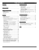
Table of Contents Introduction 3 Installation (continued) Overview ................................................................. 2 Listing Details.......................................................... 2 Safety Precautions Safety Precautions ................................................... 4 Features and Specifications Features ................................................................. 6 Installation Options................................................... 6 Heating Specifications ..
Safety Precautions Safety Warnings: • Failure to follow all of the requirements may result in property damage, bodily injury, or even death. • This unit must be installed by a qualified installer to prevent the possibility of an explosion. • This appliance must be installed in accordance with all local codes, if any; if not, in U.S.A. follow ANSI Z223.1 and NFPA 54(88).
Safety Precautions 5 Safety Warnings (continued): • Allow the heater to cool before carrying out any maintenance or cleaning. • Operate the heater according to the instructions included in this manual. • If the main burners do not start correctly turn the gas off at the gas control valve and call your dealer for service. • The pilot flame must contact the thermopile and thermocouple. If it does not, turn the gas control valve to "OFF" and call your dealer.
Features and Specifications Installation Options • • • • • • • Residential or Mobile Home Straight or Corner Placement Flush or Recessed Face Raised or Floor Placement Internal or External Chase Horizontal or Vertical Vent Bedroom Approved Heating Specifications Approximate Heating Capacity (in square feet)* Maximum BTU Input Per Hour Steady State Efficiency** (with blowers on) * ** Natural Gas Propane 1,200 to 2,250 40,000 Up to 80 % 1,200 to 2,250 39,000 Up to 81 % Heating capacity will vary
Installation 7 (for qualified installers only) Packing List • • • • Propane Conversion Kit Log Set (9 piece) Grate Wall Switch with Wire (see page 20 for details) • Firestop (sku 93006094 Additional Items Required • FIREBACKS ARE REQUIRED – See page 47. • • Direct Vent Gas Line Equipment (shutoff valve, pipe, etc.) Electrical Equipment (min. 14 gauge, grounded line) Grill or Face • • (sku 98500662, 98500663, 98500664, or 98500665) Installation Overview • All requirements below must be met.
Installation (for qualified installers only) Massachusetts Requirements NOTE: The following requirements reference various Massachusetts and national codes not contained in this document.
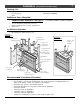
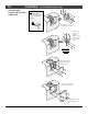
Installation 9 (for qualified installers only) Top Vent or Rear Vent Configuration This appliance is shipped in the rear vent configuration. To change to the top vent configuration, follow the directions below. NOTE: the vent configuration affects several aspects of installation (framing, maximum vent rise, maximum vent run). When reviewing the installation requirements make sure to pay attention to the type of configuration being used.
Installation Converting the Fireplace to Top Vent (continued) (for qualified installers only) NOTE: Use a magnetictipped nutdriver on these screws - take care to prevent the screws from falling into the fireplace. Remove the 12 screws securing the flue assembly. Rotate the flue assembly so the flue points upwards. Secure using the twelve screws removed earlier. DO NOT OVERTIGHTEN THE SCREWS. Attach the intake cover plate with the screws removed earlier.
Installation 11 (for qualified installers only) Fireplace Placement Requirements • The fireplace requires a 1/2" clearance from the angled sides and back of the fireplace to the framing members. No material (insulation, framing, etc.) may be placed into this area. • Fireplace must be installed on a level surface capable of supporting the fireplace and vent • Fireplace must be placed directly on wood or non-combustible surface (not on linoleum or carpet) • This heater may be placed in a bedroom.
Installation (for qualified installers only) Minimum Framing Dimensions - Rear Vent Configuration Included Firestop (required) HINT: place the fireplace so the center Part # 93006094 line is at least 5" from both vertical framing members at the rear (this allows the vent to pass through the framing without modfications) Vent Clearances (8" dia. Vent): 1" to the sides, 1" below, and 3" above the vent to combustibles.
Installation (for qualified installers only) 13 Minimum Framing Dimensions - Top Vent Configuration Minimum 49” Fireplace Enclosure Height Route the electrical line to a position to the left rear of the fireplace. 38-1/2" 41-1/4" 20" The on/off switch/thermostat wire (if used) should be routed to a location near the right front of the fireplace.
Installation (for qualified installers only) Nailing Brackets There are four nailing brackets on the front of the fireplace. Follow the directions below to prepare the nailing brackets. Once in place, nail or screw the Make sure the fireplace is nailing brackets to the framing. square and plumb when placed in the framing. Measured corner-tocorner, the fireplace NOTE: Additional nailing should be square (approx. brackets are provided along 54-7/8” for each the base of the fireplace.
Installation 15 (for qualified installers only) Corner Installations - Rear Vent Configuration A typical 45° installation uses the framing dimensions shown in the illustration below (NOTE: all clearances still apply). Travis Firestop 7-1/2" Approximate (varies due to vent installation) NOTE: Most installations use: 6" Section for 2x6 Walls 4" Section for 2x4 Walls (Travis # 98900166) 48" Min.
Installation (for qualified installers only) Corner Installations - Top Vent Configuration A typical 45° installation uses the framing dimensions shown in the illustration below (NOTE: all clearances still apply). Minimum 1/2" Clearance 15-1/2" 48" Min.
Installation 17 (for qualified installers only) Gas Line Requirements MASSACHUSETTS INSTALLATIONS - WARNING: THIS PRODUCT MUST BE INSTALLED BY A LICENSED PLUMBER OR GAS FITTER WHEN INSTALLED WITHIN THE COMMONWEALTH OF MASSACHUSETTS. OTHER MASSACHUSETTS CODE REQUIREMENTS: • Flexible connector must not be longer than 36 inches. • Shutoff valve must be a “T” handle gas cock. • Only direct vent sealed combustion products are approved for bedrooms or bathrooms.
Installation (for qualified installers only) Gas Line Location Left Side Gas Inlet (preferred) A 12" flex tube and shutoff valve is included with the fireplace. The shutoff valve accepts a 1/2"MPT. A 2" high by 3" wide opening is located behind the gas inlet cover plate (it is 2" above the base of the fireplace). The Gas Inlet is 3/8" FPT 6-3/4" You may remove this cover plate to install the gas line. The cover plate has a 7/8" diameter hole (covered with a push plug).
Installation 19 (for qualified installers only) Electrical Connection (required) • The electrical line to the grounded receptacle inside the fireplace must be installed by a qualified installer and must meet all local codes. • Make sure the household breaker is shut off prior to working on any electrical lines. • The fireplace must be properly grounded in accordance with local codes (or ANSI/NFPA 70-1987) • The electrical line must be a min.
Installation (for qualified installers only) Wall Switch or Thermostat Installation Wiring Diagram (Millivolt System) Do not connect 110-120 VAC to the gas control valve or wiring system of this fireplace. The switch must be installed by a qualified installer. The included wall switch may be installed following the directions below. An optional thermostat may also be installed. It is attached to the gas control valve in the same manner.
Installation 21 (for qualified installers only) Vent Requirements • • • • The gas appliance and vent system must be vented directly to the outside of the building, and never be attached to a chimney serving a separate solid fuel or gas-burning appliance. Each direct vent gas appliance must use it's own separate vent system. In addition to the requirements listed here, follow the requirements provided with the vent.
Installation (for qualified installers only) Approved Vent • Rear vent configurations use 8" diameter Simpson Dura-Vent Model GS vent. • Top vent configurations use 8" or 6-5/8" diameter Simpson Dura-Vent Model GS vent. If using 6-5/8" diameter vent, attach the 8" to 6-5/8" reducer (Travis part # 98900165) to the fireplace. 6-5/8" Diameter Vent Reducer - # 98900165 Vent Installation • Slide the vent sections together and turn 1/4 turn until the sections lock in place.
Installation 23 (for qualified installers only) Approved Vent Configurations Restrictor Position • Intake and exhaust restrictors are built into the appliance to adjust the flow rate of intake air and exhaust gases. Depending upon the vent configuration, you may be required to adjust the restrictor positions. The charts for acceptable vent configurations detail the correct vent restrictor positions.
Installation (for qualified installers only) Intake Restrictor Adjustment The intake restrictor is shipped in position # 1 (open). To adjust the restrictor to postion # 2 (closed, follow the instructions below. NOTE: The intake restrictor is accessed with the burner removed (see page 52). Loosen these two screws. AA AA AA This restrictor is in position # 1. Slide the intake restrictor down and re-tighten the screws to secure. AA AA AA © Travis Industries This restrictor is in position # 2.
Installation 25 (for qualified installers only) Diffuser Plate Adjustment Certain vent configurations require the diffuser plate to be adjusted (refer to the approved vent configuration charts for details). Position # 1 is stock (bent). Position # 2 is flattened. See the directions below to change the diffuser to position #2. Firebo Back W all of F x Roo irebox f Remove the exhaust restrictor. 1/4" Nutdriver 1/4" Nutdriver Remove the diffuser.
Installation (for qualified installers only) Rear Vent Configuration with Horizontal Termination (no vertical rise) • The termination must fall within the shaded area shown in the chart. Use the indicated restrictor and diffuser positions. HINT: Travis Industries provides a minimum rear vent kit (sku 98900168). It includes a 4” section and a horiztontal termination cap.
Installation 27 (for qualified installers only) Rear Vent Configuration with Horizontal Termination (with vertical rise) Up to four elbows (45° or 90°) may be used. • Only one horizontal elbow may be used. 15 feet 5 feet 20' (max) • 10 feet The termination must fall within the shaded area shown in the chart. Use the indicated restrictor and diffuser positions.
Installation (for qualified installers only) Only one horizontal elbow may be used. 20' (max) 15 feet 10 feet Exhaust Restrictor # 6 Intake Restrictor # 2 Diffuser Position # 2 35 feet 30 feet Exhaust Restrictor # 5 Intake Restrictor # 2 Diffuser Position # 2 25 feet 20 feet 15 feet 10 feet 40' (max) 35 feet 30 feet 25 feet 20 feet 15 feet 10 feet 5 feet 0 feet 0 feet 0 feet 5 feet 20' (max) • 15 feet Up to four elbows (45° or 90°) may be used.
Installation 29 (for qualified installers only) Top Vent Configuration with Horizontal Termination Up to four elbows (45° or 90°) may be used. • May use 8" or 6-5/8" diameter vent (see page for 21 details). • Only one horizontal elbow may be used. 21' (max) 20 feet 10 feet 5 feet 20' (max) • 15 feet The termination must fall within the shaded area shown in the chart. Use the indicated restrictor and diffuser positions.
Installation (for qualified installers only) Only one horizontal elbow may be used. • May use 8" or 6-5/8" diameter vent (see page for 21 details).
Installation 31 (for qualified installers only) Termination Requirements ! Venting terminals shall not be recessed into a wall or siding. A Minimum 9" clearance from any door or window B Minimum 12" above any grade, veranda, porch, deck or balcony C Minimum 1" from outside corner walls NOTE: Clearance in accordance with local installation codes and the requirements of the gas supplier. Roof Surface 11” Min. 6” Min.
Installation (for qualified installers only) Hearth Requirements Do not build a hearth more than 1” above the baseplate (this area must remain clear AAAAAAAAAAAAAAAAAA AAAAAAAAAAAAAAAAAA AAAAAAAAAAAAAAAAAA AAAAAAAAAAAAAAAAAA AAAAAAAAAAAA AAAAAAAAAAAAAAAAAA AAAAAAAAAAAA AAAAAAAAAAAAAAAAAA AAAAAAAAAAAA AAAAAAAA AAAAAAAAAAAAAAAAAA AAAAAAAAAAAA AAAAAAAA AAAAAAAAAAAAAAAAAA AAAAAAAAAAAA AAAAA AAAAAAAA AAAAAAAAAAA AAAAAAAAAAA AAAAAAAAAAAAAAAAAA AAAAAAAAAAAA AAAAA AAAAAAAA AAAAAAAAAAA AAAAAAAAAAAAAAAAAA AAAA
Installation 33 (for qualified installers only) Facing Requirements • This appliance is designed to allow for drywall (or other combustible facing) to contact the sides and top of the front of the fireplace. • Non-combustible facing (tile, masonry, etc.) must be placed over the fiber board on the front of the fireplace (see "Facing Overview" on page 34 for further details).
Installation (for qualified installers only) Facing Overview Upgrade faces are available for this fireplace and may influence facing installation. Consult with your Travis Dealer if you are using an upgrade face. Optional non-combustible facing may be installed on the fireplace. Use the guidelines below to determine the location (also see the following pages for detailed diagrams. Any non-combustible facing under 1" thick (see "Thin Facing" on page 35).
Installation 35 (for qualified installers only) Thin Facing Installation (tile, marble, or other non-combustible under 1" thick) Tile Line Upgrade faces are available for this fireplace and may influence facing installation. Consult with your Travis Dealer if you are using an upgrade face.
Installation (for qualified installers only) Thin Facing Installation (tile, marble, under 1" thick) - Side View Raised Fireplace (with no Hearth) AAA A AAA A AAA A AAA A AAA A AAA A AAA A AAA A AAA A AAA A A AAA AAA AA AAA AAA A AAA A AAA A AAA A AAA A AAA A AAA A AAA A AAA A AAA A AAA A AAA A AAA A AAA AA A AA AAAA AA A Drywall Tile (or other facing under 1” thick) Face SIDE OF FIREPLACE AAA AAA AAA AAA AAA AAA AAA AAA Floor-Mounted Fireplace with Hearth Note how the facing extends 1” above t
Installation 37 (for qualified installers only) Thick Facing Installation (stone, brick, or other non-combustible over 1" thick) Masonry Line If using a Fireplace Xtrordinair (FPX) arched face, see "Thick Facing with a Fireplace Xtrordinair Arched Faces" on page 38.
Installation (for qualified installers only) Thick Facing with Fireplace Xtrordinair (FPX) Arched Faces The following illustration shows facing considerations for those fireplaces utilizing FPX arched faces. The facing must be non-combustible and over 1" in depth. The Fireplace Xtrordinair 864 Masonry Template is recommended for masonry installation (sku 98500688). The template helps locate and support the masonry as it being installed.
Installation 39 (for qualified installers only) Thick Facing Installation - Side View Floor-Mounted Fireplace with Hearth AA AA AA AA AA A AA AAAAA AAAAA AA AA A AA A AA AAAAA AA A AA A AAA AAA AA A AAA AA A AAA AAAAA AAAA AA AA AA AA A AAAAA AA AA A AA AA A AA AA A AA AA A AA AA A AA AA A AAAAA AA AA A AA AA A AAAAAA AA AA AA AA A AA AA A AA AA A AAAAA Drywall Masonry (or other non-combustible over 1” thick) SIDE OF FIREPLACE Face Hearth (note how it extends under the face max. 1” thick).
Installation (for qualified installers only) Mantel Requirements • The illustration below details mantel clearances and maximum mantel depth. • Any material that protrudes more than 3/4” from the non-combustible facing is considered a mantel and must meet the mantel requirements.
Installation 41 (for qualified installers only) Installation Example - Build-Out (Dog-House) with Horizontal Termination • The framing, facing, and other building materials depicted below are for example only. Refer to local building codes for framing, facing, and insulating requirements in your area.
Installation (for qualified installers only) Installation Example - Build-In with Horizontal Termination • The framing, facing, and other building materials depicted below are for example only. Refer to local building codes for framing, facing, and insulating requirements in your area.
Finalizing the Installation (for qualified installers only) 43 Steps for Finalizing the Installation 1. Remove the glass (see page 45). NOTE: If using propane (LP) convert the appliance prior to installing the logs. 2. We recommend you purge the gas line at this time (with the glass removed). This allows gas to be detected once it enters the firebox, ensuring gas does not build up. 3. Install the logs (see page 47). 4. Turn on the gas to the fireplace. Turn on gas to the heater.
Finalizing the Installation (for qualified installers only) 8. Check the air shutter following the directions below. Air Shutter Adjustment Let the heater burn for fifteen minutes (make sure the logs and glass are in place). The flames should be yellow with no sooting. Adjust the air shutter, if necessary, to achieve the correct looking flame. Correct Not Enough Air Too Much Air Flames should be blue at the base, yellow-orange on the top.
Finalizing the Installation (for qualified installers only) 45 Glass Frame Removal and Installation a Warning: The appliance must be completely cool before removing the glass. Warning: Do not strike or slam the glass. Based upon the face being used, either: (a) swing the access door down and remove the top grill, (b) remove the face (unscrew or lift off - see the instructions included with the face for details).
Finalizing the Installation (for qualified installers only) Glass Frame Removal and Installation (continued) The latch can come loose from glass frame anchor. This occurs when it is turned 1/4 turn when it is disengaged. Follow the directions below to re-install the latch if it becomes loose. Hold the latch at an angle and insert it into the slot on the glass frame anchor. Latch NOTE: this slot may be at a different angle than illustrated.
Finalizing the Installation (for qualified installers only) 47 Fireback and Grate Installation WARNING: Firebacks are required for this fireplace and must be installed prior to operation. 1 Remove the glass frame. 3 Remove the exhaust restrictor (see page 23). Make sure to return the restrictor to the correct position after the firebacks are in place. 4 Install the firebacks and grate following the directions below. b Place the rear fireback in place.
Finalizing the Installation (for qualified installers only) Log Set Installation Rear Log Installation These pins insert into the holes on the bottom of the rear log. Log Stop (both sides) Place the rear log in place and slide it all the way back against the log stops. Right Log Installation The burner has a flat portion here with a ridge directly behind it. Place the right log on the flat portion of the burner and push it back so it rests against the ridge.
Finalizing the Installation (for qualified installers only) 49 Left Log Installation This hole and pin are not utilized. Place the left log so this pin inserts into the hole on the bottom of the log. When in place, the logs should look like this.
Finalizing the Installation (for qualified installers only) Left Twig Installation This hole is not utilized. Place the left twig so the hole and slot fit over the pins on the rear and left log. Right Twig Installation Place the right twig so the hole fits over the pin on the rear log. Move the front end of the right twig to the right. It should be resting on the middle portion of the right log.
Finalizing the Installation (for qualified installers only) 51 Center Twig Installation Place the center twig on the flat portion of the burner. Front Twigs Installation Place the front twigs along the front of the grate as shown (exact placement is not mandatory – make sure the twigs do not line up over any burner holes). NOTE: If using the optional andirons, you may need to adjust twig placement. Ember Installation A bag of embers is provided to further enhance the firebox.
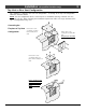
Finalizing the Installation (for qualified installers only) LP Conversion Instructions Install the conversion kit prior to installing the gas line to ensure proper gas use. 1 Remove the glass (see page 45). Remove the logs and coals (if installed - page 47). Remove the grate and firebacks (see page 47). 2 Remove the burner (see illustration below). Remove the four screws holding the burner assembly in place. AA A Slide the burner to the left and up to remove.
Finalizing the Installation 3 (for qualified installers only) 53 Follow the directions below to replace the orifices. a Slide the air shutters all the way to the left. A AAA A AAA AAA Rear Orifice Front Orifice Manifold b c Use a 1/2” open end wrench to unscrew both orifices. 1/2" Wrench Apply thread sealant to the LP orifices prior to installation. Use the chart below to identify the correct orifices.
Finalizing the Installation 5 Replace the firebox components. Install the logs and embers. Replace the glass. (for qualified installers only) a Remove and discard the three screws using a slotted screwdriver of Torx T-20. 6 Remove the regulator from the front of the gas control valve. Replace with the propane regulator, using the new gasket and screws included with the regulator. NOTE: Leak test this area after the heater is installed, gas is connected, and the main burner is lit.
Optional Equipment 55 (for qualified installers only) Grill Installation Certain faces allow for installation of an upper and lower grill. Follow the directions below to install. Upper Grill Installation Hold the grill at an angle and insert the lower slot over the bushing on the fireplace (both sides). You may need press on the grill to get the tab over the bushing (this prevents the grill from accidentally falling off). Swing the grill upwards to engage the second slot.
Optional Equipment (for qualified installers only) Remote Control Receiver Installation (2 Options) The instructions below detail installation of the optional remote control receiver. For operating instructions, refer to the instructions included with the remote. OPTION # 1 - Remote Thermostat (99300653) WARNING: Make sure the power cord does not contact the blower (if applicable) or the Attach the power cord to the bottom of firebox (or other hot surface).
Optional Equipment 57 (for qualified installers only) Extra Room Power Heat Duct (sku 98500769) Special Instructions for 864 HH Newer 864 HH fireplaces (SN 3407-001010 or later) have an improved wiring harness and removable heat shields below the heat duct connections. The wiring harness is now routed through the snap disk, allowing the power heat duct to be turned on and off by the fireplace (see “Wiring Instructions” on page 62).
Optional Equipment (for qualified installers only) Installation Overview The optional heat duct allows the fireplace to transfer heat to separate locations in the home. Installation should take place prior to installing drywall. Warning: This kit must be installed as specified in these instructions. Do not modify any component. Warning: Use of any external blower other than the Travis Power Heat Duct Blower will void the warranty and listing of this appliance and may create a fire hazard.
Optional Equipment 59 (for qualified installers only) Duct Installation Instructions AAAAAAAAAAAAAAAAAA AAAAAAAAA AAAAAAAAA AAAAAAAAAAAAAAAAAA AAAAAAAAA AAAAAAAAAAAAAAAAAA A A A AA AAAAAAAAA A AAAAAAAAAAAAAAAAAA A AAAAAAAAAAAAAAAAAA A A A AA A A A A A A A A AA A A A A A A A A AAAAAA AAAAAAAAAAAAAAAAAA A A A A A AA A A AA A AA A A A A A A AA AA A AA A A A A AAAAAAAAAAAAAAAAAAA A A A AA AAAAAAAAAAAAAAAAAA A A A A Determine the route for the heat duct using the illustration below as a guide.
Optional Equipment (for qualified installers only) Floor Mounting a Cut a hole between floor joists for the blower box. AAAA AAAA A AAAA A b Attach the floor boot to the blower box with the included screws. The screws attach to either of these pairs of holes. Use the upper pair for thick flooring, the lower pair for thin flooring. 5-1/4" c 14" Slide the blower into the hole cut in step "a". Attach with four screws.
Optional Equipment 61 (for qualified installers only) Install the air duct. Each section, when joined, must be attached with three screws and aluminum duct tape (U.L. 181A-P or equivalent). Secure the duct if it is in an area where it may sag or become dislodged. NOTE: The air duct has a 0” clearance to combustibles. Secure all ducting together with screws. Then seal the seams with aluminum duct tape (U.L. 181A-P or equivalent). AA AA AA AA AA Attach the grill (and wall adapter, if necessary).
Optional Equipment (for qualified installers only) Wiring Instructions Warning: All wiring should be done by a qualified electrician and shall be in compliance with local codes and with the current National Electric Code ANSI/NFPA 70. Warning: Make sure the fireplace electrical circuit is disabled prior to working on electrical hookup. Wiring Diagram - 864 HH*, 44 DV XXL, & 36 DV * SN 3407-001010 or greater.
Optional Equipment 2 63 (for qualified installers only) Follow the directions below to wire the rheostat. NOTE: There are two types of junction boxes, use the appropriate junction box for your installation. a Force the sheathed cable through one of the locking flaps on the junction box (repeat for the other cable). Some force is needed. The flap will lock the cable in place. From Blower Box Attach the common (white) wires together. Attach the ground (exposed or green) wires together.
Optional Equipment Accent Light Installation (for qualified installers only) (sku 94400100) Make sure power to the fireplace has been turned off prior to installation (disable the service breaker). Do not connect 110-120 VAC to the gas control valve or the on/off circuit on this fireplace. The accent light must be removed to install the rear fireback. The remaining firebacks are installed after the accent light is in place. 1 Remove the firebacks (if already installed – see page 47).
Optional Equipment 4 65 (for qualified installers only) Install the strain relief plate to the firebox floor following the directions below. a Insert the four wires through the strain relief plate (NOTE: Put the b larger, male connectors through Secure the wires using the included strain relief (wrap the strain relief over the wires, compress with pliers, then insert into the hole). first).
Optional Equipment (for qualified installers only) Optional Wall-Mounted Rheostat NOTE: Many areas require all wiring to be installed by a qualified electrician. Check with your local building official for any requirements in your area. 1 Remove the rheostat from the rheostat assembly. 2 Detach the three wires leading from the rheostat (secured with wire nuts). Attach the rheostat assembly to the fireplace (see the illustration on the previous page).
Optional Equipment © Travis Industries (for qualified installers only) 4080214 67 100-01182_003
Index Index Additional Items Required............................................ 7 Air Shutter Adjustment ................................................ 44 Altitude Considerations ............................................... 21 Approved Vent Configurations ...................................... 23 Approved Vent ........................................................... 22 Clearances................................................................