BayRS Version 14.00 Part No. 308625-14.
Copyright © 1999 Nortel Networks All rights reserved. Printed in the USA. September 1999. The information in this document is subject to change without notice. The statements, configurations, technical data, and recommendations in this document are believed to be accurate and reliable, but are presented without express or implied warranty. Users must take full responsibility for their applications of any products specified in this document.
Nortel Networks NA Inc. Software License Agreement NOTICE: Please carefully read this license agreement before copying or using the accompanying software or installing the hardware unit with pre-enabled software (each of which is referred to as “Software” in this Agreement). BY COPYING OR USING THE SOFTWARE, YOU ACCEPT ALL OF THE TERMS AND CONDITIONS OF THIS LICENSE AGREEMENT. THE TERMS EXPRESSED IN THIS AGREEMENT ARE THE ONLY TERMS UNDER WHICH NORTEL NETWORKS WILL PERMIT YOU TO USE THE SOFTWARE.
for the security of its own data and information and for maintaining adequate procedures apart from the Software to reconstruct lost or altered files, data, or programs. 4. Limitation of liability.
Contents Preface Before You Begin ............................................................................................................. xv Text Conventions .............................................................................................................xvi Acronyms ........................................................................................................................xvii Related Publications ...............................................................................
Customizing a GRE Tunnel ...........................................................................................1-16 Disabling and Reenabling a GRE Tunnel ...............................................................1-16 Disabling and Reenabling a Protocol on a GRE Tunnel .........................................1-18 Deleting a Protocol from a GRE Tunnel .................................................................1-19 Disabling and Reenabling a Remote Tunnel End Point ............................
Using Site Manager ................................................................................................2-20 Enabling NAT Synchronization ........................................................................2-20 Adding NAT Synchronization Peers .................................................................2-21 Customizing NAT Global Parameters ...........................................................................2-22 Enabling and Disabling NAT on the Router ............................
Configuring NAT Synchronization Peers .......................................................................2-65 Adding NAT Synchronization Peers .......................................................................2-65 Enabling and Disabling NAT Synchronization Peers ..............................................2-67 Deleting NAT Synchronization Peers .....................................................................2-69 Chapter 3 Configuring RIPSO on an IP Interface RIPSO Concepts and Terminology ..
Appendix A Site Manager Parameters GRE Parameters ........................................................................................................... A-2 GRE Tunnel Parameters ......................................................................................... A-2 Remote Connection Parameters ............................................................................. A-4 NAT Parameters ............................................................................................................
Figures Figure 1-1. Simple GRE Tunnel Components ............................................................1-3 Figure 1-2. GRE Tunnel Encapsulating the IP Protocol .............................................1-5 Figure 2-1. Network Address Translation Example ....................................................2-4 Figure 2-2. NAT Detects the Source Address ............................................................2-5 Figure 2-3. NAT Updates the Local/Global Translation Entry List ............
Tables Table 2-1. NAT Log Message Types ......................................................................2-26 Table 4-1. BFE X.25 Packet-Level Parameter Settings .............................................4-5 Table 4-2. BFE X.25 Network Service Record Parameter Settings ..........................4-7 308625-14.
Preface This guide describes the following services and what you do to start and customize them on a Nortel Networks™ router: • Generic Routing Encapsulation (GRE) tunnels • Network Address Translation (NAT) • Basic Revised IP Security Option (RIPSO) security labels • Blacker front-end device connections You can use Site Manager to configure any of these services on a router. You can also use the Bay Command Console (BCC™) to configure GRE and NAT.
Configuring GRE, NAT, RIPSO, and BFE Services Text Conventions This guide uses the following text conventions: angle brackets (< >) Indicate that you choose the text to enter based on the description inside the brackets. Do not type the brackets when entering the command. Example: If the command syntax is: ping , you enter: ping 192.32.10.12 bold text Indicates command names and options and text that you need to enter. Example: Enter show ip {alerts | routes}. Example: Use the dinfo command.
Preface separator ( > ) Shows menu paths. Example: Protocols > IP identifies the IP option on the Protocols menu. vertical line ( | ) Separates choices for command keywords and arguments. Enter only one of the choices. Do not type the vertical line when entering the command. Example: If the command syntax is: show ip {alerts | routes}, you enter either: show ip alerts or show ip routes, but not both.
Configuring GRE, NAT, RIPSO, and BFE Services TCP Transmission Control Protocol UDP User Datagram Protocol VPN virtual private network WAN wide area network Related Publications For more information about GRE, NAT, and other IP services, refer to the following publications: • Reference for BCC IP show commands (Nortel Networks part number 308603-14.
Preface You can purchase selected documentation sets, CDs, and technical publications through the collateral catalog. The catalog is located on the World Wide Web at support.baynetworks.com/catalog.html and is divided into sections arranged alphabetically: • The “CD ROMs” section lists available CDs. • The “Guides/Books” section lists books on technical topics. • The “Technical Manuals” section lists available printed documentation sets.
Chapter 1 Configuring GRE Tunnels This chapter provides information about Generic Routing Encapsulation (GRE) tunnels and instructions for configuring them: Topic Page GRE Concepts and Terminology 1-2 Creating a GRE Tunnel 1-8 Customizing a GRE Tunnel 1-16 Deleting a GRE Tunnel 1-23 308625-14.
Configuring GRE, NAT, RIPSO, and BFE Services GRE Concepts and Terminology Generic Routing Encapsulation (GRE) is a protocol that allows transport of non-IP traffic through IP-based systems. GRE, which is defined in RFCs 1701 and 1702, encapsulates Internet Protocol (IP) and other layer 3 protocols to enable data transmission through an IP tunnel.
Configuring GRE Tunnels How GRE Tunneling Works A simple point-to-point GRE tunnel terminates at router interfaces at each end of the tunnel (Figure 1-1). Each of these interfaces has at least two addresses: a physical address and one or more logical addresses. The physical address, which is always an IP address, is visible to the devices making up the intervening network cloud.
Configuring GRE, NAT, RIPSO, and BFE Services The GRE tunnel can use any IP interface configured on the router as a physical end point. To maximize the robustness of the tunnel, use a circuitless IP address as a tunnel’s physical end point whenever possible. Because a circuitless IP address is associated with the whole router, not one physical interface, the tunnel operates as long as any slot that has a working IP interface stays up.
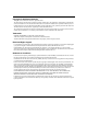
Configuring GRE Tunnels Router 2 Router 1 Internet/Intranet Host 1 Router interface 10.0.0.1 8.0.0.2 Host 2 Tunnel interface Tunnel Router interface interface MAC header Source IP address Destination IP address MAC header Source IP address Destination IP address data 10.0.0.1 8.0.0.2 data MAC header 11.0.0.10 Source IP address 11.0.0.20 Destination IP address GRE header 10.0.0.1 Source IP address 8.0.0.2 Destination address data Key Transport protocol Passenger protocol IP0064A Figure 1-2.
Configuring GRE, NAT, RIPSO, and BFE Services Requirements for GRE Tunnels Encapsulating IP Note: If you are using GRE tunneling to encapsulate the IPX or OSI protocol, skip this section. The requirements discussed below do not apply to tunnels encapsulating IPX or OSI. Before configuring a tunnel encapsulating IP, you should be aware of a limitation inherent in the use of all tunnels, including GRE tunnels.
Configuring GRE Tunnels The disadvantage of using an announce policy is that it prevents the advertisement of other subnets within the blocked range. Depending on the network topology, this configuration may not be desirable. Accept Policies An accept policy governs the addition of new routes to the routing tables.
Configuring GRE, NAT, RIPSO, and BFE Services Creating a GRE Tunnel You can create up to 64 GRE tunnels on one router; each GRE tunnel can have multiple end points. You can configure up to 256 remote tunnel end points distributed over the configured GRE tunnels. To create a tunnel, you must: 1. Create the local tunnel end point. 2. Add one or more protocols to the local tunnel end point. 3. Configure the remote tunnel end point. These steps are described in the following sections.
Configuring GRE Tunnels For example, the following command sequence creates the tunnel boston with the local physical end point 197.1.2.3 and verifies the addition: tunnels# gre name boston local-address 197.1.2.3 gre/boston# info name boston local-address 197.1.2.3 state enabled 3. Go to “Adding a Protocol to the Local Tunnel End Point” on page 1-10. Using Site Manager To create a GRE tunnel, complete the following tasks: Site Manager Procedure You do this System responds 1.
Configuring GRE, NAT, RIPSO, and BFE Services Adding a Protocol to the Local Tunnel End Point The Nortel Networks implementation of GRE tunneling supports the encapsulation of the IP and IPX protocols over a GRE tunnel. When you add a protocol to a tunnel, you are configuring its local logical interface. The local logical interface is the address of the local host, the tunnel’s local logical end point. This address is not visible to the network cloud that the tunnel passes through.
Configuring GRE Tunnels Adding an IPX Protocol Interface To add an IPX protocol interface to a GRE tunnel, navigate to the GRE tunnel interface prompt (for example, box; tunnels; gre/boston) and enter: ipx address
host-address address is a valid IPX network ID. Enter a 4-byte hexadecimal string of up to 8 characters. host_address is a valid IPX host address that is unique within the IPX internetwork. Enter up to four characters in hexadecimal format.Configuring GRE, NAT, RIPSO, and BFE Services Site Manager Procedure (continued) You do this System responds 6. Enter the required information to configure You return to the GRE Create Tunnels the IP or IPX interface. List window. For information about any parameter, click on Help or see the appropriate protocol guide. 7. Go to “Configuring the Remote Tunnel End Point” on page 1-12 to configure the remote end point of the tunnel.
Configuring GRE Tunnels Using the BCC To configure a remote tunnel end point, you must: 1. Configure the remote physical end point. 2. Configure the remote logical interface. Step 1. Configuring a Remote Physical End Point To configure a remote tunnel end point, navigate to the GRE tunnel interface prompt (for example, box; tunnels; gre/boston) and enter: remote-endpoint address name is the unique name for the remote end of the tunnel.
Configuring GRE, NAT, RIPSO, and BFE Services Step 2. Configuring a Remote Logical Interface Using the BCC, you can configure a logical interface for a remote end point. Configuring a Remote Logical IP Interface To configure a remote logical IP interface, navigate to the remote GRE tunnel interface prompt (for example, box; tunnels; gre/boston; remote-endpoint/ austin) and enter: logical-ip-address
address is a valid IP address expressed in dotted-decimal notation.Configuring GRE Tunnels Using Site Manager To configure a remote tunnel end point, complete the following tasks: Site Manager Procedure You do this System responds 1. In the Configuration Manager window, choose Protocols. The Protocols menu opens. 2. Choose IP. The IP menu opens. 3. Choose GRE. The GRE Create Tunnels List window opens. 4. Choose a tunnel from the list and click on Remote Conn. The GRE Remote Connections List window opens. 5. Click on Add.
Configuring GRE, NAT, RIPSO, and BFE Services Customizing a GRE Tunnel You can customize a configured GRE tunnel as described in the following sections: Topic Page Disabling and Reenabling a GRE Tunnel 1-16 Disabling and Reenabling a Protocol on a GRE Tunnel 1-18 Deleting a Protocol from a GRE Tunnel 1-19 Disabling and Reenabling a Remote Tunnel End Point 1-20 Deleting a Remote Tunnel End Point 1-21 Disabling and Reenabling a GRE Tunnel When you create a GRE tunnel, the tunnel is enabled by def
Configuring GRE Tunnels Using Site Manager To disable or reenable a GRE tunnel, complete the following tasks: Site Manager Procedure You do this System responds 1. In the Configuration Manager window, choose Protocols. The Protocols menu opens. 2. Choose IP. The IP menu opens. 3. Choose GRE. The GRE Create Tunnels List window opens. 4. Select a tunnel from the list. 5. Set the Enable parameter. Click on Help or see the parameter description on page A-4. 6. Click on Apply.
Configuring GRE, NAT, RIPSO, and BFE Services Disabling and Reenabling a Protocol on a GRE Tunnel When you configure a protocol interface on a GRE tunnel, the interface is enabled by default. You can use the BCC or Site Manager to disable or reenable it. Note: If you want to add a second interface to the tunnel -- IP or IPX -- see “Adding a Protocol to the Local Tunnel End Point” on page 1-10.
Configuring GRE Tunnels Site Manager Procedure (continued) You do this System responds 5. Set the Enable parameter. 6. Click on Done. You return to the Configuration Manager window. Deleting a Protocol from a GRE Tunnel Use the BCC or Site Manager to delete a protocol from a GRE tunnel. Using the BCC To delete a protocol from a GRE tunnel, navigate to the protocol interface prompt (for example, box; tunnels; gre/boston; ip/9.9.9.1/255.255.255.
Configuring GRE, NAT, RIPSO, and BFE Services Disabling and Reenabling a Remote Tunnel End Point When you configure a remote tunnel end point, it is enabled by default. You can use the BCC or Site Manager to disable or reenable the remote tunnel end point. Note: If you want to add another remote tunnel end point for the tunnel, see “Configuring the Remote Tunnel End Point” on page 1-12.
Configuring GRE Tunnels Using Site Manager To disable or reenable a remote tunnel end point, complete the following tasks: Site Manager Procedure You do this System responds 1. In the Configuration Manager window, choose Protocols. The Protocols menu opens. 2. Choose IP. The IP menu opens. 3. Choose GRE. The GRE Create Tunnels List window opens. 4. Click on Remote Conn. The GRE Remote Connections List window opens. 5.
Configuring GRE, NAT, RIPSO, and BFE Services Using Site Manager To delete a remote tunnel end point, complete the following tasks: Site Manager Procedure 1-22 You do this System responds 1. In the Configuration Manager window, choose Protocols. The Protocols menu opens. 2. Choose IP. The IP menu opens. 3. Choose GRE. The GRE Create Tunnels List window opens. 4. Click on Remote Conn. The GRE Remote Connections List window opens. 5.
Configuring GRE Tunnels Deleting a GRE Tunnel Use the BCC or Site Manager to delete a GRE tunnel from the router. Using the BCC To delete a GRE tunnel, navigate to the GRE tunnel interface prompt (for example, box; tunnels; gre/boston) and enter the following command: delete For example, the following command deletes the tunnel boston: gre/boston# delete tunnels# Using Site Manager To delete a GRE tunnel, complete the following tasks: Site Manager Procedure You do this System responds 1.
Chapter 2 Configuring Network Address Translation This chapter describes NAT and provides instructions for configuring NAT on a router.
Configuring GRE, NAT, RIPSO, and BFE Services NAT Concepts and Terminology Network Address Translation (NAT) offers a solution to two problems facing companies that require Internet access: • The diminishing number of available IP addresses for Internet hosts • Private networks with unregistered addresses that cannot access the Internet Using NAT, you can create a pool of registered IP network addresses that the router maps to your unregistered local addresses.
Configuring Network Address Translation How NAT Works In the example that follows, company A uses NAT to obtain global Internet access for its hosts. Hosts on company A’s network need access to resources in company B’s network. Company B is located in a different network on the Internet. Its addresses are registered. NAT is configured on the router bordering company A’s network and the global network.
Configuring GRE, NAT, RIPSO, and BFE Services In Figure 2-1, a packet from company A’s network with unregistered source address 10.0.0.15 is sent to a destination address in company B’s network. The destination is a globally recognized registered address, 192.100.20.2. The packet follows normal IP routing to the NAT border router at the egress point in company A. Company A Company B Registered destination address 50.1.1.52 192.100.20.2 Boston 10.0.0.50 15.0.0.
Configuring Network Address Translation When the router’s NAT interface receives a packet, the NAT router extracts the source address, first checking whether the packet’s source address falls within a configured local address range. If it does, NAT compares the source address against existing address translation entries in an internal table. In Figure 2-2, the NAT router detects a packet on a NAT interface that contains the address 10.0.0.15.
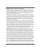
Configuring GRE, NAT, RIPSO, and BFE Services In Figure 2-3, the NAT router dynamically translates the source address, 10.0.0.15, to one of the available global addresses (in this case, 192.55.10.3) and creates a new entry in the local/global translation entry list. Current local/global mapping entry list: NAT router Local address range list Global address range list 10.0.0.0 to 10.255.255.255 192.55.10.0 to 192.55.10.255 15.0.0.0 to 15.255.255.255 192.20.10.0 to 192.20.10.255 10.0.0.1 10.0.0.2 10.
Configuring Network Address Translation In Figure 2-4, the NAT router then replaces the local source address (10.0.0.15) with the translated global address (192.55.10.3) and sends the packet on its way to its destination in company B’s network. NAT router Global address range list Local address range list 10.0.0.0 to 10.255.255.255 192.55.10.0 to 192.55.10.255 15.0.0.0 to 15.255.255.255 192.20.10.0 to 192.20.10.255 Current local/global mapping entry list: 10.0.0.1 10.0.0.2 10.0.0.15 192.55.10.1 192.
Configuring GRE, NAT, RIPSO, and BFE Services The destination host uses the incoming packet’s source address to create a destination address to send a packet back to the sending host. When the packet arrives at company A’s NAT router: 1. The NAT router checks the packet’s destination address. If it is a global address from a configured global address range, NAT compares the destination address to entries in its translation table. 2.
Configuring Network Address Translation Static Address Translation Using static address translation, you can create a one-to-one translation of an unregistered local host address to a global address. A static address translation mapping does not time out, but remains configured until you disable or delete it. For instructions on how to create and enable static translation, see “Configuring Static Address Translation” on page 2-38.
Configuring GRE, NAT, RIPSO, and BFE Services A router does not “own” a translation unless it receives traffic using that translation. If a router does not own a translation, it cannot delete it unless it receives a deletion update from a peer router. The example in Figure 2-5 shows two NAT routers configured as peers. Company A Company B 50.1.1.52 192.100.20.2 Boston 10.0.0.50 15.0.0.20 London New York Springfield (NAT router 1) New York Atlanta 10.0.0.1 Springfield (NAT router 2) Santa Clara 10.
Configuring Network Address Translation Starting NAT Services You can use the BCC or Site Manager to start NAT on the router. For instructions on how to start and use the BCC or Site Manager, see one of these guides: • • Using the Bay Command Console (BCC) Configuring and Managing Routers with Site Manager Using the BCC To get NAT up and running on a router using default values for most parameters: 1. Add NAT to the router. 2. Specify at least one local address range to be translated. 3.
Configuring GRE, NAT, RIPSO, and BFE Services To configure a local address range, navigate to the global NAT prompt (for example, box; ip; nat) and enter: nat# local-range
/ address is the base local address expressed in dotted-decimal notation. mask is the prefix length associated with the IP address expressed in decimal notation.Configuring Network Address Translation Configuring a Global NAT Interface The global interface is connected to the external internetwork. IP packets arriving at the global interface from the outside internetwork may be looked up and translated if necessary. To specify the global NAT interface, navigate to the appropriate IP interface prompt (for example, box; ethernet/2/1; ip/192.132.22.10/255.255.255.0) and enter: nat At the NAT interface prompt (for example, nat/192.132.22.
Configuring GRE, NAT, RIPSO, and BFE Services Using Site Manager Before you can start NAT on the router, you must configure a circuit that the protocol can use as an interface to an attached network. For information and instructions, see Configuring Ethernet, FDDI, and Token Ring Services or Configuring WAN Line Services. To start NAT on a router using Site Manager: 1. Configure NAT on the router and on the local IP interface. 2. Configure NAT on the global interface. 3.
Configuring Network Address Translation Site Manager Procedure (continued) You do this System responds 8. Click on OK to accept the default interface You return to the Circuit Definition type for NAT (local). window. 9. Choose File. The File menu opens. 10. Choose Exit. You return to the Configuration Manager window. Configuring the Global Interface The global interface is connected to the external internetwork.
Configuring GRE, NAT, RIPSO, and BFE Services Configuring a Local and Global Address Range The local address range tells the router which local unregistered host addresses to translate into global addresses. The global address range tells the router which registered global addresses to use when translating local addresses.You must configure at least one local and one global address range. You specify a local and a global address range as a base address and a prefix length (from 1 through 32 decimal).
Configuring Network Address Translation Site Manager Procedure (continued) You do this System responds 12. Choose NAT. The NAT menu opens. 13. Choose Dynamic. The NAT Dynamic menu opens. 14. Choose Global. The NAT Global Address Range List window opens. 15. Click on Add. The NAT Global Address Range Add window opens. 16. Set the following parameters: • IP Address • Prefix Length Click on Help or see the parameter descriptions beginning on page A-20. 17. Click on OK.
Configuring GRE, NAT, RIPSO, and BFE Services Starting NAT Synchronization NAT synchronization allows up to 10 routers configured as peers to share NAT address translation information. Routers in a synchronized configuration have up-to-date address translation tables and can handle traffic that may be rerouted to them if a peer router should shut down or fail. To configure NAT synchronization, you configure each router as follows: 1. Start NAT on the router (see “Starting NAT Services” on page 2-11). 2.
Configuring Network Address Translation Using the BCC To start NAT synchronization on a router using default values for most parameters: 1. Enable NAT synchronization on the router. 2. Specify at least one synchronization peer. Enabling NAT Synchronization You must configure an IP interface on the router before you can enable NAT synchronization. To enable NAT synchronization, navigate to the global NAT prompt (for example, box; ip; nat) and enter: synch enabled [synch-router-id ] n.n.n.
Configuring GRE, NAT, RIPSO, and BFE Services Configuration Example The following example shows the BCC commands that you enter to configure NAT synchronization using an already configured IP interface as the synchronized router ID: box# ip; nat nat# synch enabled nat# peer 10.0.0.20 address 10.0.0.20 Using Site Manager You must configure an IP interface on the router before enabling NAT synchronization.
Configuring Network Address Translation Adding NAT Synchronization Peers To add a router to the list of synchronized peer routers, complete the following tasks: Site Manager Procedure You do this System responds 1. In the Configuration Manager window, choose Protocols. The Protocols menu opens. 2. Choose IP. The IP menu opens. 3. Choose NAT. The NAT menu opens. 4. Choose Synch Peer. The NAT Synchronization Peer List window opens. 5. Click on Add. The NAT Synchronization Peer Add window opens.
Configuring GRE, NAT, RIPSO, and BFE Services Customizing NAT Global Parameters To customize the way NAT operates on a router, modify NAT global attributes as described under the following sections: 2-22 Topic Page Enabling and Disabling NAT on the Router 2-23 Configuring the Soloist Slot Mask 2-24 Logging NAT Messages 2-26 Enabling and Disabling Translation Entry Timeout 2-28 Configuring the Translation Entry Timeout Value 2-29 308625-14.
Configuring Network Address Translation Enabling and Disabling NAT on the Router You can use the BCC or Site Manager to enable or disable NAT on the router. Using the BCC To enable or disable NAT on a router, navigate to the global NAT prompt (for example, box; ip; nat) and enter: state state is one of the following: enabled (default) disabled Using Site Manager To enable or disable NAT on a router, complete the following tasks: Site Manager Procedure You do this System responds 1.
Configuring GRE, NAT, RIPSO, and BFE Services Configuring the Soloist Slot Mask By default, the router uses any available slot for the NAT soloist. Use the BCC or Site Manager to specify which slots can run as the NAT soloist. Using the BCC To specify the slots on which NAT can run as a soloist, navigate to the global NAT prompt (for example, box; ip; nat) and enter: slot-mask slot can be one or more slots from 1 through 14.
Configuring Network Address Translation Using Site Manager To specify the slots on which NAT can run as a soloist, complete the following tasks: Site Manager Procedure You do this System responds 1. In the Configuration Manager window, choose Protocols. The Protocols menu opens. 2. Choose IP. The IP menu opens. 3. Choose NAT. The NAT menu opens. 4. Choose Global. The NAT Base Group Record window opens. 5. Click in the Soloist Slot Mask field. 6. Click on Values.
Configuring GRE, NAT, RIPSO, and BFE Services Logging NAT Messages By default, the router does not log NAT messages. You can enable the logging of messages by specifying the types of messages that the router should log. Table 2-1 lists the message types that can be logged by NAT software. If you enable logging, the change is effective immediately (if there are any messages to be logged). Table 2-1.
Configuring Network Address Translation Using Site Manager To specify the types of log messages that are reported by NAT software, complete the following tasks: Site Manager Procedure You do this System responds 1. In the Configuration Manager window, choose Protocols. The Protocols menu opens. 2. Choose IP. The IP menu opens. 3. Choose NAT. The NAT menu opens. 4. Choose Global. The NAT Base Group Record window opens. 5.
Configuring GRE, NAT, RIPSO, and BFE Services Enabling and Disabling Translation Entry Timeout By default, the router deletes expired NAT translation table entries. If there have been no translated packets for a specific address mapping when the translation entry timer expires, NAT software removes the entry from the dynamic translation entry list, freeing the global address for another mapping.
Configuring Network Address Translation Configuring the Translation Entry Timeout Value A dynamic translation entry (or mapping) has an associated “last-use” value that increases each second that it is unused. Every time the entry is used, its last-use value is reset to 0. If the translation timer is enabled, and the last-use value meets or exceeds the translation entry timeout value, then the translation is deleted and the global IP address is available for reuse.
Configuring GRE, NAT, RIPSO, and BFE Services Using Site Manager To configure the timeout period for a dynamic translation entry, complete the following tasks: Site Manager Procedure You do this System responds 1. In the Configuration Manager window, choose Protocols. The Protocols menu opens. 2. Choose IP. The IP menu opens. 3. Choose NAT. The NAT menu opens. 4. Choose Global. The NAT Base Group Record window opens. 5. Set the Max Timeout parameter.
Configuring Network Address Translation Customizing a NAT Interface This section includes the following topics: Topic Page Adding NAT to an IP Interface 2-31 Enabling and Disabling NAT on an Interface 2-33 Modifying the Interface Type 2-35 Deleting NAT from an IP Interface 2-37 Adding NAT to an IP Interface Use the BCC or Site Manager to add NAT to an IP interface.
Configuring GRE, NAT, RIPSO, and BFE Services Using Site Manager To add NAT to an IP interface, complete the following tasks: Site Manager Procedure You do this System responds 1. In the Configuration Manager window, The Edit Connector window opens. click on the connector to which you want to add NAT services. 2. Click on Edit Circuit. The Circuit Definition window opens. 3. Choose Protocols. The Protocols menu opens. 4. Choose Add/Delete. The Select Protocols window opens. 5. Click on NAT.
Configuring Network Address Translation Enabling and Disabling NAT on an Interface When you add NAT to an IP interface, NAT is enabled by default. You can use the BCC or Site Manager to enable or disable NAT. Using the BCC To enable or disable NAT on an interface, navigate to the NAT interface prompt (for example, box; ethernet/13/1; ip/1.2.3.4/255.0.0.
Configuring GRE, NAT, RIPSO, and BFE Services Using Site Manager To enable or disable NAT on an interface, complete the following tasks: Site Manager Procedure You do this System responds 1. In the Configuration Manager window, choose Protocols. The Protocols menu opens. 2. Choose IP. The IP menu opens. 3. Choose NAT. The NAT menu opens. 4. Choose Interface. The NAT Interface List window opens. 5. Select the interface that you want to enable or disable from the list. 6. Set the Enable parameter.
Configuring Network Address Translation Modifying the Interface Type The NAT router is configured with local and global interfaces. Local interfaces are attached to the local network. When a packet arrives at the local interface, the NAT router examines the packet’s source address to determine whether it should be translated into a global address before forwarding. Global interfaces are attached to the external network.
Configuring GRE, NAT, RIPSO, and BFE Services Using Site Manager To modify the NAT interface type, complete the following tasks: Site Manager Procedure You do this System responds 1. In the Configuration Manager window, choose Protocols. The Protocols menu opens. 2. Choose IP. The IP menu opens. 3. Choose NAT. The NAT menu opens. 4. Choose Interface. The NAT Interface List window opens. 5. Select the interface that you want to modify from the list. 6. Set the Interface Type parameter.
Configuring Network Address Translation Deleting NAT from an IP Interface Use the BCC or Site Manager to delete NAT from an IP interface. Using the BCC To delete NAT from an interface, navigate to the NAT interface prompt (for example, box; ethernet/13/1; ip/1.2.3.4/255.0.0.0; nat/1.2.3.4) and enter: delete For example, the following command deletes NAT from IP interface 1.2.3.4/ 255.0.0.0: ip/1.2.3.4/255.0.0.0# nat nat/1.2.3.4# delete ip/1.2.3.4/255.0.0.
Configuring GRE, NAT, RIPSO, and BFE Services Configuring Static Address Translation Static address translation creates a one-to-one mapping of an unregistered local host address to a registered global address. Static address mappings can be used to: • Preserve a translation entry. • Create a connection from a host on the global network to a host on the local network. A static address translation does not time out when there is no traffic on the interface.
Configuring Network Address Translation For example, the following command sequence maps the local address 10.1.1.1 to the global address 199.1.42.200 and verifies the entry: nat# static-map 10.1.1.1/199.1.42.200 static-map/10.1.1.1/199.1.42.200# info local-address 10.1.1.1 global-address 199.1.42.200 protocol none local-port 0 global-port 0 state enabled Note: The parameters protocol, local-port, and global-port are reserved for future use. You cannot modify these parameters.
Configuring GRE, NAT, RIPSO, and BFE Services Enabling and Disabling a Static Address Mapping When you add a static address mapping, it is enabled by default. You can use the BCC or Site Manager to disable or reenable it. Using the BCC To enable or disable a static address mapping, navigate to the static map prompt (for example, box; ip; nat; static-map/10.1.1.1/199.1.42.
Configuring Network Address Translation Using Site Manager To enable or disable a static address mapping, complete the following tasks: Site Manager Procedure You do this System responds 1. In the Configuration Manager window, choose Protocols. The Protocols menu opens. 2. Choose IP. The IP menu opens. 3. Choose NAT. The NAT menu opens. 4. Choose Static. The NAT Static Translation List window opens. 5. Select the static mapping that you want to enable or disable from the list. 6.
Configuring GRE, NAT, RIPSO, and BFE Services Using Site Manager To delete a static address mapping, complete the following tasks: Site Manager Procedure You do this System responds 1. In the Configuration Manager window, choose Protocols. The Protocols menu opens. 2. Choose IP. The IP menu opens. 3. Choose NAT. The NAT menu opens. 4. Choose Static. The NAT Static Translation List window opens. 5. Select the static mapping that you want to delete. 2-42 6. Click on Delete.
Configuring Network Address Translation Configuring Dynamic Local Address Ranges The local address range is a group of unregistered source addresses used for address translations. When NAT software detects an outbound packet from an address within a configured local address range, it maps the local address to a global address, replaces the packet’s local address with the global address, and sends the packet to its destination address in another network.
Configuring GRE, NAT, RIPSO, and BFE Services Using Site Manager To configure a local address range, complete the following tasks: Site Manager Procedure You do this System responds 1. In the Configuration Manager window, choose Protocols. The Protocols menu opens. 2. Choose IP. The IP menu opens. 3. Choose NAT. The NAT menu opens. 4. Choose Dynamic. The NAT Dynamic menu opens. 5. Choose Local. The NAT Local Address Range List window opens. 6. Click on Add.
Configuring Network Address Translation Enabling and Disabling a Local Address Range When you add a local address range, it is enabled by default. You can use the BCC or Site Manager to disable or reenable it. Using the BCC To disable or reenable a local address range, navigate to the local address range prompt (for example, box; ip; nat; local-range/10.1.10.
Configuring GRE, NAT, RIPSO, and BFE Services Using Site Manager To disable or reenable a local address range, complete the following tasks: Site Manager Procedure You do this System responds 1. In the Configuration Manager window, choose Protocols. The Protocols menu opens. 2. Choose IP. The IP menu opens. 3. Choose NAT. The NAT menu opens. 4. Choose Dynamic. The NAT Dynamic menu opens. 5. Choose Local. The NAT Local Address Range List window opens. 6.
Configuring Network Address Translation Deleting a Local Address Range You can use the BCC or Site Manager to delete a dynamic local address range. Using the BCC To delete a local address range, navigate to the local address range prompt (for example, box; ip; nat; local-range/10.1.10.0/24) and enter: delete For example, the following command deletes the local address range 10.1.10.0/24: local-range/10.1.10.
Configuring GRE, NAT, RIPSO, and BFE Services Configuring Dynamic Global Address Ranges The global address range is a group of registered source addresses used for address translations. When NAT software detects an outbound packet from an address within a configured local address range, it maps the local address to a global address, replaces the packet’s local address with the global address, and sends the packet to its destination address in another network.
Configuring Network Address Translation Using Site Manager To configure a global address range, complete the following tasks: Site Manager Procedure You do this System responds 1. In the Configuration Manager window, choose Protocols. The Protocols menu opens. 2. Choose IP. The IP menu opens. 3. Choose NAT. The NAT menu opens. 4. Choose Dynamic. The NAT Dynamic menu opens. 5. Choose Global. The NAT Global Address Range List window opens. 6. Click on Add.
Configuring GRE, NAT, RIPSO, and BFE Services Enabling and Disabling a Global Address Range When you create a global address range, it is enabled by default. You can use the BCC or Site Manager to disable or reenable it. Using the BCC To disable or reenable a global address range, navigate to the global address range prompt (for example, box; ip; nat; global-range/199.1.2.
Configuring Network Address Translation Using Site Manager To disable or reenable a global address range, complete the following tasks: Site Manager Procedure You do this System responds 1. In the Configuration Manager window, choose Protocols. The Protocols menu opens. 2. Choose IP. The IP menu opens. 3. Choose NAT. The NAT menu opens. 4. Choose Dynamic. The NAT Dynamic menu opens. 5. Choose Global. The NAT Global Address Range List window opens. 6.
Configuring GRE, NAT, RIPSO, and BFE Services Deleting a Global Address Range Use the BCC or Site Manager to delete a dynamic global address range. Using the BCC To delete a global address range, navigate to the global address range prompt (for example, box; ip; nat; global-range/197.1.2.0/24) and enter: delete For example, the following command deletes the global address range 197.1.2.0/24: global-range/197.1.2.
Configuring Network Address Translation Configuring Network Address Port (N-to-1) Translation Using network address port (N-to-1) translation, you can map many local addresses to one global address. Note: N-to-1 translation is valid only for TCP/UDP packets. All non-TCP/ UDP packets with addresses that fall within the configured local address range are dropped. When NAT receives a packet on the local interface, the following events occur: 1.
Configuring GRE, NAT, RIPSO, and BFE Services The following events occur: 1. NAT receives a packet from host A on the local interface with a local source address of 55.0.0.1 and a port number of 2001. 2. Determining that the local source address falls within the range configured for N-to-1 translation, NAT stores the port number, replaces the local source address with the global address, 192.1.1.
Configuring Network Address Translation Host A Host B NAT N-to-1 translator Local destination address: 55.0.0.1 Port: 2001 Host A Global destination address: 192.1.1.1 Port: 12000 Host B NAT N-to-1 translator Local destination address: 55.0.0.2 Port: 2222 Global destination address: 192.1.1.1 Port: 54000 IP0076A Figure 2-7. N-to-1 Translation (Global to Local) 3. Subsequently, NAT receives a packet on the global interface with the destination address 192.1.1.1 and port number 54000.
Configuring GRE, NAT, RIPSO, and BFE Services Using the BCC To configure N-to-1 translation: 1. Configure a local address range (see “Adding a Local Address Range” on page 2-43). 2. Navigate to the local address range prompt (for example, box; ip; nat; local-range/10.1.10.0/24) and enter: n-to-1 global_address is the IP address to be used in this N-to-1 translation entered in dotted-decimal notation. For example, the following command sequence configures the IP address 199.1.42.
Configuring Network Address Translation Using Site Manager To configure N-to-1 translation, complete the following tasks: Site Manager Procedure You do this System responds 1. In the Configuration Manager window, choose Protocols. The Protocols menu opens. 2. Choose IP. The IP menu opens. 3. Choose NAT. The NAT menu opens. 4. Choose Dynamic. The NAT Dynamic menu opens. 5. Choose Local. The NAT Local Address Range List window opens. 6. Select a local address range from the list.
Configuring GRE, NAT, RIPSO, and BFE Services Customizing NAT Synchronization Parameters To customize the way NAT synchronization operates on a router, modify NAT global attributes as described under the following sections: Topic Page Enabling and Disabling NAT Synchronization 2-58 Setting the Synchronized Router ID 2-60 Setting the Synchronization Port 2-62 Customizing Keepalive Parameters 2-63 Enabling and Disabling NAT Synchronization NAT synchronization allows up to 10 routers to share NAT ad
Configuring Network Address Translation If you enable synchronization without entering a synchronized router ID, the router automatically inserts the IP address of an existing router IP interface. For example, in the following series of commands, the IP address of the previously configured IP interface 197.1.2.3 is used when synchronization is enabled: nat# info slot-mask {1 2 3 4 5 6 7 8 9 10 11 12 13 14} log-mask none timeout enabled synch disabled synch-router-id 0.0.0.
Configuring GRE, NAT, RIPSO, and BFE Services Using Site Manager You must configure an IP interface on the router before enabling NAT synchronization. If none are configured, you cannot enable synchronization. If an IP interface already exists, you will be prompted to select that interface as the synchronized router ID. To enable NAT synchronization, complete the following tasks: Site Manager Procedure You do this System responds 1. In the Configuration Manager window, choose Protocols.
Configuring Network Address Translation Using the BCC To set a synchronized router ID, navigate to the global NAT prompt (for example, box; ip; nat) and enter: synch-router-id For example, the following command configures the router with the synchronized router ID 10.1.2.3: nat# synch-router-id 10.1.2.3 Using Site Manager To configure a synchronized router ID, complete the following tasks: Site Manager Procedure You do this System responds 1.
Configuring GRE, NAT, RIPSO, and BFE Services Setting the Synchronization Port The default TCP port value for connections between synchronized NAT peers is 670. To use a different TCP port value for NAT synchronization, select an unused TCP port. The same TCP port value must be configured on all peer routers in a synchronized configuration. You can enter a value from 0 through 16640. Note: Do not change the port value after synchronization is enabled.
Configuring Network Address Translation Customizing Keepalive Parameters NAT synchronization uses keepalive messages to recognize and close terminated connections between synchronized peers. If a peer fails or disconnects without notification, the keepalive mechanism lets the router detect the termination and close the connection at its end. You can customize the NAT synchronization keepalive mechanism by changing the default values for the following: • Keepalive interval.
Configuring GRE, NAT, RIPSO, and BFE Services To reset the keepalive retry count, navigate to the global NAT prompt and enter: synch-retransmit-tries count is any integer. To configure the router to send only one keepalive message, enter 0.
Configuring Network Address Translation Configuring NAT Synchronization Peers NAT synchronization peers are the routers that this router exchanges translation updates with. When the NAT router receives a connection request, it looks up the sending router’s ID in its list of peers. If the sending router’s ID is not in its peer list, the router refuses the connection request. Adding NAT Synchronization Peers NAT synchronization supports up to 10 routers in a synchronized configuration.
Configuring GRE, NAT, RIPSO, and BFE Services Using Site Manager To add a router to the list of synchronized peer routers, complete the following tasks: Site Manager Procedure You do this System responds 1. In the Configuration Manager window, choose Protocols. The Protocols menu opens. 2. Choose IP. The IP menu opens. 3. Choose NAT. The NAT menu opens. 4. Choose Synch Peer. The NAT Synchronization Peer List window opens. 5. Click on Add. The NAT Synchronization Peer Add window opens. 6.
Configuring Network Address Translation Enabling and Disabling NAT Synchronization Peers Enabling a peer allows this router to send translation updates to and accept them from the peer. Disabling a peer immediately terminates any connections that this router may have to that peer. Use the BCC or Site Manager to enable or disable synchronization peers. Using the BCC To enable or disable a peer router, navigate to the peer prompt (for example, box; ip; nat; peer/10.0.0.
Configuring GRE, NAT, RIPSO, and BFE Services Using Site Manager To enable or disable a peer router, complete the following tasks: Site Manager Procedure You do this System responds 1. In the Configuration Manager window, choose Protocols. The Protocols menu opens. 2. Choose IP. The IP menu opens. 3. Choose NAT. The NAT menu opens. 4. Choose Synch Peer. The NAT Synchronization Peer List window opens. 5. Select the peer from the list. 6. Set the Peer Disable parameter.
Configuring Network Address Translation Deleting NAT Synchronization Peers Use the BCC or Site Manager to delete synchronization peers. Using the BCC To delete a NAT synchronization peer, navigate to the peer prompt (for example, box; ip; nat; peer/10.0.0.20) and enter: delete For example, the following command deletes the peer 10.0.0.20: peer/10.0.0.20# delete nat# Using Site Manager To delete a peer router, complete the following tasks: Site Manager Procedure You do this System responds 1.
Chapter 3 Configuring RIPSO on an IP Interface This chapter describes RIPSO and provides instructions for configuring RIPSO on an IP interface. RIPSO Concepts and Terminology IP routers support the Department of Defense (DoD) Revised IP Security Option (RIPSO), as defined in RFC 1108, on a per-interface basis. RFC 1108 specifies both “basic” and “extended” security options; the Nortel Networks implementation supports only the basic option.
Configuring GRE, NAT, RIPSO, and BFE Services By default, RIPSO is disabled on IP interfaces.
Configuring RIPSO on an IP Interface The format of the security label is as follows: • Octet 1 contains a type value of 82(16), identifying the basic security option format. • Octet 2 specifies the length of the option (three or more octets, depending on the presence or absence of authority flags). • Octet 3 specifies the security classification levels for the datagrams.
Configuring GRE, NAT, RIPSO, and BFE Services Inbound IP Datagrams When the router receives an IP datagram on a RIPSO interface, it compares the security classification and authority values specified in the security label with those configured on the inbound interface. If the interface does not require a security label for inbound IP datagrams, the router accepts both unlabeled IP datagrams and datagrams that meet the classification and authority rules described in the next paragraph.
Configuring RIPSO on an IP Interface Originated IP Datagrams When the router originates a datagram and the following conditions are true, the router labels the datagram with the default security label before transmitting it: • The datagram needs forwarding through a RIPSO interface. • The RIPSO interface requires outbound labels for originated datagrams.
Configuring GRE, NAT, RIPSO, and BFE Services Enabling and Disabling RIPSO Use Site Manager to enable or disable RIPSO on an interface. When you disable RIPSO, the router accepts only the following IP datagrams: labeled IP datagrams with the classification level set to Unclassified and no authority flags set, and unlabeled IP datagrams. Site Manager Procedure You do this System responds 1. In the Configuration Manager window, choose Protocols. The Protocols menu opens. 2. Choose IP. The IP menu opens.
Configuring RIPSO on an IP Interface Specifying the IP Datagram Type for Stripping Security Options Use Site Manager to choose the type of IP datagram from which you want IP security options to be removed. Options are: • None. The router leaves IP security options on all inbound and outbound IP datagrams intact. • Incoming. The router strips the IP security option from each incoming IP datagram after checking the IP datagram against the interface’s security configuration. • Outgoing.
Configuring GRE, NAT, RIPSO, and BFE Services Specifying the Outbound Datagram Type Requiring Security Labels Use Site Manager to specify the type of outbound datagrams that require IP security labels. Options are: • None. The router forwards unlabeled IP datagrams unchanged on this interface. In addition, those IP datagrams that it originates and transmits do not require labels. • Forwarded.
Configuring RIPSO on an IP Interface Specifying the Inbound Datagram Type Requiring Security Labels Use Site Manager to specify the type of inbound datagrams that require IP security labels. Options are: • None. Inbound IP datagrams are not required to contain labels. • All. All inbound IP datagrams received on this interface must contain basic IP security options. Site Manager Procedure You do this System responds 1. In the Configuration Manager window, choose Protocols. The Protocols menu opens.
Configuring GRE, NAT, RIPSO, and BFE Services Setting the Security Level for IP Datagrams Use Site Manager to specify the minimum and maximum security level that the router allows for inbound or outbound IP datagrams. The minimum and maximum security level features specify the range of classification levels that the router will accept and process. The router drops IP datagrams received on this interface that are below the minimum and above the maximum levels that you specify.
Configuring RIPSO on an IP Interface Choosing Authority Flags in Outbound Datagrams Use Site Manager to specify which authority flags must be set, and which authority flags may be set in the protection authority field of all outbound datagrams. Site Manager Procedure You do this System responds 1. In the Configuration Manager window, choose Protocols. The Protocols menu opens. 2. Choose IP. The IP menu opens. 3. Choose Interfaces. The IP Interface List window opens. 4.
Configuring GRE, NAT, RIPSO, and BFE Services Choosing Authority Flags in Inbound Datagrams Use Site Manager to specify which authority flags must be set, and which authority flags may be set in the protection authority field of all inbound datagrams. Site Manager Procedure You do this System responds 1. In the Configuration Manager window, choose Protocols. The Protocols menu opens. 2. Choose IP. The IP menu opens. 3. Choose Interfaces. The IP Interface List window opens. 4.
Configuring RIPSO on an IP Interface Supplying Implicit Labels for Unlabeled Inbound Datagrams Use Site Manager to specify whether the router should supply implicit labels to unlabeled inbound datagrams received by an interface. The router uses the values of the Implicit Authority and Implicit Level parameters to create an implicit label. By default, implicit labeling is enabled. Site Manager Procedure You do this System responds 1. In the Configuration Manager window, choose Protocols.
Configuring GRE, NAT, RIPSO, and BFE Services Enabling and Disabling Default Labels for Unlabeled Outbound Datagrams Use Site Manager to specify whether you want the router to supply a default label to unlabeled outbound datagrams originated or forwarded out this interface. The router uses the values of the Default Authority and Default Level parameters to create a default label. Site Manager Procedure You do this System responds 1. In the Configuration Manager window, choose Protocols.
Configuring RIPSO on an IP Interface Enabling and Disabling Error Labels for Outbound ICMP Error Datagrams Use Site Manager to specify whether you want the router to supply an error label to outbound ICMP error datagrams. The router uses the values of the Error Authority and the Minimum Level parameters to create an error label. Site Manager Procedure You do this System responds 1. In the Configuration Manager window, choose Protocols. The Protocols menu opens. 2. Choose IP. The IP menu opens. 3.
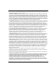
Configuring GRE, NAT, RIPSO, and BFE Services RIPSO Example The router in Figure 3-2 has RIPSO configured on all three IP interfaces. The security ranges specified for each interface vary, as shown. (For simplicity, this example assumes that none of the interfaces requires any authority flags on inbound and outbound traffic, but any flags that are present are acceptable.) When host 1.1.0.
Configuring RIPSO on an IP Interface Interface Min. Security Classification Max. Security Classification 1.1.0.2 Unclassified Top secret 1.2.0.2 Secret Top secret 1.3.0.2 Top secret Top secret IP datagram 1.1.0.1 Secret IP data... 1.1.0.1 Accept inbound datagram? Yes 1.1.0.2 1.2.0.2 1.2.0.1 Forward outbound datagram? Yes 1.3.0.2 Forward outbound datagram? No 1.3.0.1 IP0014A Figure 3-2. 308625-14.
Chapter 4 Connecting the Router to a Blacker Front End This chapter describes the Blacker front end (BFE) and provides instructions for configuring the BFE on a router. Blacker Front End (BFE) Concepts and Terminology The BFE is a classified encryption device used by hosts to communicate across unsecured wide area networks (WANs). BFE devices are typically found in government networks (for example, DSNET), which handle sensitive data requiring a greater degree of security.
Configuring GRE, NAT, RIPSO, and BFE Services Router BFE X.25 DDN BFE Router BFE Key Black network Red network Figure 4-1. Router IP0015A BFE Network Configuration BFE devices receive authorization and address translation services from an access control center (ACC) residing on the black network. The ACC makes access control decisions that determine which hosts are allowed to communicate with each other.
Connecting the Router to a Blacker Front End BFE Addressing You can enable BFE support on individual IP interfaces. Once enabled, the router uses the BFE address-resolution algorithm to map IP addresses to corresponding X.121 addresses. BFE IP-to-X.121 address translation differs from standard DDN address translation. Each physical router-to-BFE connection is identified by a BFE X.121 network address and a BFE IP address. The format of a BFE X.
Configuring GRE, NAT, RIPSO, and BFE Services Configuring BFE Support To configure BFE support on an IP interface, you must: • Configure an X.25 interface that conforms to the BFE requirements described in this section. • Enable the IP routing protocol on the interface. • Enable RIPSO support on the interface. Beginning at the Configuration Manager window, perform the following procedures: 1. Configure an X.25 interface. When you initially configure packet-level parameters for the X.
Connecting the Router to a Blacker Front End For instructions on performing steps 1 through 4, see Configuring X.25 Services. For instructions on performing step 5, see Configuring IP, ARP, RARP, RIP, and OSPF Services. For instructions on performing step 6, see Chapter 3, “Configuring RIPSO on an IP Interface.” Note: Generally, the synchronous line parameter settings are the same for both a DDN X.25 link and a BFE X.25 link.
Configuring GRE, NAT, RIPSO, and BFE Services Table 4-1. BFE X.25 Packet-Level Parameter Settings (continued) Parameter Setting Outgoing SVC LCN Start Parameter is ignored. Number of PVC channels Zero (0). BFE does not support PVCs. PVC LCN Start Parameter is ignored. T1 Timer, T2 Timer, T3 Timer, T4 Timer BFE has no special requirements for any of these four parameters. Flow Control Negotiation Set to on if you do not want to use the default values configured in the BFE for this link.
Connecting the Router to a Blacker Front End Table 4-1. BFE X.25 Packet-Level Parameter Settings (continued) Parameter Setting Full Addressing On Acceptance Format Defext Release Format Defext CCITT (now ITU-T) Conformance DXE1980 Network Standard DOD Table 4-2. BFE X.25 Network Service Record Parameter Settings Parameter Setting Enable Enable Type DDN Connection ID Parameter is ignored. Remote IP Address Specify the IP address of the remote system. Remote X.
Configuring GRE, NAT, RIPSO, and BFE Services Table 4-2. BFE X.25 Network Service Record Parameter Settings (continued) 4-8 Parameter Setting Packet Size Options include 128, 256, 512, and 1024. If you want to use a value other than the default packet size configured in the BFE, set Flow Facility to on. (If the IP interface is configured to support multiple IP security levels, then set to 1024.) You must coordinate this value with the packet-level value.
Appendix A Site Manager Parameters This appendix contains the Site Manager parameter descriptions for GRE, NAT, and RIPSO. You can display the same information using Site Manager online Help.
Configuring GRE, NAT, RIPSO, and BFE Services The Technician Interface allows you to modify parameters by issuing set and commit commands with the MIB object ID. This process is equivalent to modifying parameters using Site Manager. For more information about using the Technician Interface to access the MIB, see Using Technician Interface Software. Caution: The Technician Interface does not verify the validity of your parameter values. Entering an invalid value can corrupt your configuration.
Site Manager Parameters To access the GRE Create Tunnels List window, complete the following tasks: Site Manager Procedure You do this System responds 1. In the Configuration Manager window, choose Protocols. The Protocols menu opens. 2. Choose IP. The IP menu opens. 3. Choose GRE. The GRE Create Tunnels List window opens.
Configuring GRE, NAT, RIPSO, and BFE Services Parameter: Enable Path: Default: Options: Function: Instructions: MIB Object ID: Configuration Manager > Protocols > IP > GRE Enabled Enabled | Disabled Enables or disables the tunnel. Set to Enable to enable the tunnel. Set to Disable to disable the tunnel. 1.3.6.1.4.1.18.3.5.3.2.1.27.1.2 Remote Connection Parameters The Create GRE Remote Connection window (Figure A-2) allows access to parameters that configure remote tunnel end points. Figure A-2.
Site Manager Parameters To access the Create GRE Remote Connection window, complete the following tasks: Site Manager Procedure You do this System responds 1. In the Configuration Manager window, choose Protocols. The Protocols menu opens. 2. Choose IP. The IP menu opens. 3. Choose GRE. The GRE Create Tunnels List window opens. 4. Choose a tunnel from the list and click on Remote Conn. The GRE Remote Connections List window opens. 5. Click on Add. The Create GRE Remote Connection window opens.
Configuring GRE, NAT, RIPSO, and BFE Services Parameter: Remote Physical IP Address Path: Default: Options: Function: Configuration Manager > Protocols > IP > GRE > Remote Conn 0.0.0.0 IP interface address Specifies the IP address of the physical router interface at the remote end of the GRE tunnel. This address is visible to the network cloud that the tunnel passes through. Instructions: Enter an IP address in dotted-decimal notation. MIB Object ID: 1.3.6.1.4.1.18.3.5.3.2.1.28.1.
Site Manager Parameters NAT Parameters NAT parameters are described in the following sections: Topic Page NAT Global Parameters A-7 NAT Interface Parameters A-12 NAT Static Translation Parameters A-14 NAT Dynamic Translation Local Address Range Parameters A-17 NAT Dynamic Translation Global Address Range Parameters A-19 NAT Synchronization Peer Parameters A-21 NAT Global Parameters The NAT Base Group Record window (Figure A-3) allows access to NAT global configuration parameters. Figure A-3.
Configuring GRE, NAT, RIPSO, and BFE Services To access the NAT Base Group Record window, complete the following tasks: Site Manager Procedure You do this System responds 1. In the Configuration Manager window, choose Protocols. The Protocols menu opens. 2. Choose IP. The IP menu opens. 3. Choose NAT. The NAT menu opens. 4. Choose Global. The NAT Base Group Record window opens.
Site Manager Parameters Parameter: Log Mask Path: Default: Options: Function: Instructions: MIB Object ID: Configuration Manager > Protocols > IP > NAT > Global None Any number of message types specified using a bit mask Specifies the types of log messages that are reported by NAT software. Click on Values and select the message types that you want to log. 1.3.6.1.4.1.18.3.5.3.2.7.1.
Configuring GRE, NAT, RIPSO, and BFE Services Parameter: Synchronization Path: Default: Options: Function: Configuration Manager > Protocols > IP > NAT > Global Disable Enable | Disable Enables or disables NAT synchronization. Enabling synchronization allows this router to receives translation updates from peer routers. If this router is configured with address ranges and peers, enabling synchronization also allows this router to send translation updates.
Site Manager Parameters Parameter: Keep Alive Interval Path: Default: Options: Function: Configuration Manager > Protocols > IP > NAT > Global 120 seconds 0 to 2,147,483,647 Specifies the synch keepalive interval in seconds. When a TCP connection to a peer router remains idle for this period of time, the router sends a keepalive message to the peer. Setting the timer to 0 turns off the synch keepalive function. Instructions: Specify an interval value. MIB Object ID: 1.3.6.1.4.1.18.3.5.3.2.7.1.
Configuring GRE, NAT, RIPSO, and BFE Services NAT Interface Parameters The NAT Interface List window (Figure A-4) allows access to NAT interface parameters. Figure A-4. NAT Interface List Window To access the NAT Interface List window, complete the following tasks: Site Manager Procedure A-12 You do this System responds 1. In the Configuration Manager window, choose Protocols. The Protocols menu opens. 2. Choose IP. The IP menu opens. 3. Choose NAT. The NAT menu opens. 4. Choose Interface.
Site Manager Parameters Parameter: Enable Path: Default: Options: Function: Instructions: Configuration Manager > Protocols > IP > NAT > Interface Enable Enable | Disable Enables or disables NAT on an IP interface. Set to Enable to enable NAT on an IP interface. Set to Disable to disable NAT on an IP interface. MIB Object ID: 1.3.6.1.4.1.18.3.5.3.2.7.6.1.
Configuring GRE, NAT, RIPSO, and BFE Services NAT Static Translation Parameters The NAT Static Translation List window (Figure A-5) allows access to NAT static mapping parameters. Figure A-5. NAT Static Translation List Window To access the NAT Static Translation List window, complete the following tasks: Site Manager Procedure A-14 You do this System responds 1. In the Configuration Manager window, choose Protocols. The Protocols menu opens. 2. Choose IP. The IP menu opens. 3. Choose NAT.
Site Manager Parameters Parameter: Local Address Path: Default: Options: Function: Instructions: MIB Object ID: Configuration Manager > Protocols > IP > NAT > Static > Add None Local IP address Specifies the local address for a static mapping pair. Enter the appropriate IP address in dotted-decimal notation. 1.3.6.1.4.1.18.3.5.3.2.7.4.1.
Configuring GRE, NAT, RIPSO, and BFE Services Parameter: Mapping Protocol Path: Default: Options: Function: Instructions: MIB Object ID: Configuration Manager > Protocols > IP > NAT > Static 0 None Specifies the IP protocol of the static mapping pair. This parameter is reserved for future use. Do not change this value. 1.3.6.1.4.1.18.3.5.3.2.7.4.1.
Site Manager Parameters NAT Dynamic Translation Local Address Range Parameters The NAT Local Address Range List window (Figure A-6) allows access to NAT local address range parameters. Figure A-6. NAT Local Address Range List Window To access the NAT Local Address Range List window, complete the following tasks: Site Manager Procedure You do this System responds 1. In the Configuration Manager window, choose Protocols. The Protocols menu opens. 2. Choose IP. The IP menu opens. 3. Choose NAT.
Configuring GRE, NAT, RIPSO, and BFE Services Parameter: IP Address Path: Default: Options: Function: Configuration Manager > Protocols > IP > NAT > Dynamic > Local > Add None Local IP address Together with the prefix length, specifies a local address range. NAT maps a local address within this range to a registered global address. Instructions: Enter the appropriate IP address in dotted-decimal notation. MIB Object ID: 1.3.6.1.4.1.18.3.5.3.2.7.3.1.
Site Manager Parameters Parameter: Nto1 Address Path: Default: Options: Function: Configuration Manager > Protocols > IP > NAT > Dynamic > Local None Any global IP address Specifies a global IP address for N-to-1 translation. NAT translates all addresses in the selected local range into this global IP address. Instructions: Enter a global IP address in dotted-decimal notation. MIB Object ID: 1.3.6.1.4.1.18.3.5.3.2.7.3.1.
Configuring GRE, NAT, RIPSO, and BFE Services To access the NAT Global Address Range List window, complete the following tasks: Site Manager Procedure You do this System responds 1. In the Configuration Manager window, choose Protocols. The Protocols menu opens. 2. Choose IP. The IP menu opens. 3. Choose NAT. The NAT menu opens. 4. Choose Dynamic. The Local/Global menu opens. 5. Choose Global. The NAT Global Address Range List window opens.
Site Manager Parameters Parameter: Enable Path: Default: Options: Function: Configuration Manager > Protocols > IP > NAT > Dynamic > Global Enable Enable | Disable Enables or disables a global address range. The NAT router maps local addresses to registered global addresses. Instructions: Set to Enable to enable the global address range. Set to Disable to disable the global address range. MIB Object ID: 1.3.6.1.4.1.18.3.5.3.2.7.2.1.
Configuring GRE, NAT, RIPSO, and BFE Services To access the NAT Synchronization Peer List window, complete the following tasks: Site Manager Procedure You do this System responds 1. In the Configuration Manager window, choose Protocols. The Protocols menu opens. 2. Choose IP. The IP menu opens. 3. Choose NAT. The NAT menu opens. 4. Choose Synch Peer. The NAT Synchronization Peer List window opens.
Site Manager Parameters Parameter: Peer Address Path: Default: Options: Function: Instructions: MIB Object ID: Configuration Manager > Protocols > IP > NAT > Synch Peer None Any valid IP address Specifies the IP address of the peer router. Enter a valid IP address for the peer in dotted-decimal notation. 1.3.6.1.4.1.18.3.5.3.2.7.7.1.6 308625-14.
Configuring GRE, NAT, RIPSO, and BFE Services RIPSO Parameters The IP Interface List window (Figure A-9) allows access to parameters that configure RIPSO on a router interface. Figure A-9. IP Interface List Window To access the IP Interface List window, complete the following tasks: Site Manager Procedure You do this System responds 1. In the Configuration Manager window, choose Protocols. The Protocols menu opens. 2. Choose IP. The IP menu opens. 3. Choose Interfaces.
Site Manager Parameters Parameter: Enable Security Path: Default: Options: Function: Instructions: Configuration Manager > Protocols > IP > Interfaces Enable Enable | Disable Enables or disables IP security options for this interface. Set to Disable if you want to disable IP security options. If you set this parameter to Disable, the router accepts only the following IP datagrams: labeled IP datagrams with the classification level set to Unclassified and no authority flags set, and unlabeled IP datagrams.
Configuring GRE, NAT, RIPSO, and BFE Services Parameter: Require Out Security Path: Default: Options: Function: Instructions: Configuration Manager > Protocols > IP > Interfaces All None | Forwarded | Originated | All Specifies which type of outbound datagrams require IP security labels. Select None: the router forwards unlabeled IP datagrams unchanged on this interface. In addition, those IP datagrams that it originates and transmits do not require labels.
Site Manager Parameters Parameter: Minimum Level Path: Default: Options: Function: Configuration Manager > Protocols > IP > Interfaces Unclassified Unclassified | Confidential | Secret | Top Secret Specifies the minimum security level that the router allows for inbound or outbound IP datagrams. This parameter, together with the Maximum Level parameter, specifies the range of classification levels that the router will accept and process.
Configuring GRE, NAT, RIPSO, and BFE Services Parameter: Must Out Authority Path: Default: Options: Function: Configuration Manager > Protocols > IP > Interfaces No authority flags selected No authority flags selected | GENSER | SIOPESI | SCI | NSA | DOE Specifies which authority flags must be set in the protection authority field of all outbound datagrams. Instructions: Select all authority flags that the router must set in all outbound IP datagrams that it transmits on this interface.
Site Manager Parameters Parameter: Must In Authority Path: Default: Options: Function: Configuration Manager > Protocols > IP > Interfaces No authority flags selected No authority flags selected | GENSER | SIOPESI | SCI | NSA | DOE Specifies which authority flags must be set in the protection authority field of inbound IP datagrams. Instructions: Select all authority flags that must be set in inbound IP datagrams received on this interface.
Configuring GRE, NAT, RIPSO, and BFE Services Parameter: Implicit Label Path: Default: Options: Function: Configuration Manager > Protocols > IP > Interfaces Enable Enable | Disable If you select Enable, the router uses the Implicit Authority and Implicit Level fields to create an implicit label. The router supplies the implicit label to unlabeled inbound datagrams received by this interface. If you select Disable, the router does not supply implicit labels for this interface.
Site Manager Parameters Parameter: Implicit Level Path: Default: Options: Function: Configuration Manager > Protocols > IP > Interfaces Unclassified Unclassified | Confidential | Secret | Top Secret Specifies the security level that the router sets when it supplies implicit security labels for unlabeled, inbound IP datagrams. Instructions: Specify a level within the range specified by the Minimum Level and Maximum Level parameters. MIB Object ID: 1.3.6.1.4.1.18.3.5.3.2.1.4.
Configuring GRE, NAT, RIPSO, and BFE Services Parameter: Default Authority Path: Default: Options: Function: Configuration Manager > Protocols > IP > Interfaces No authority flags selected No authority flags selected | GENSER | SIOPESI | SCI | NSA | DOE Specifies the authority flags that the router uses when it supplies default security labels to unlabeled outbound IP datagrams. Instructions: Select authority flags that the router should set when it supplies default security labels.
Site Manager Parameters Parameter: Error Label Path: Default: Options: Function: Configuration Manager > Protocols > IP > Interfaces Enable Enable | Disable If you select Enable, the router uses the Error Authority and Minimum Level fields to create an error label. The router supplies the error label to outbound ICMP error datagrams. If you select Disable, the router does not supply error labels for this interface.
Index A accept policies, configuring for GRE tunnels, 1-6, 1-7 D acronyms, xvii Default Authority parameter (RIPSO), 3-14, A-32 announce policies, configuring for GRE tunnels, 1-6 Default Label parameter (RIPSO), 3-14, A-31 authority flags (RIPSO) inbound datagrams, 3-12 outbound datagrams, 3-11 default labels (RIPSO) defined, 3-5 enabling or disabling use of, 3-14 authority values (RIPSO), 3-4 Default Level parameter (RIPSO), 3-14, A-32 B BFE.
dynamic address translation (NAT) configuring, 2-48 defined, 2-8 starting, 2-11 E Enable parameter GRE remote tunnel end point, 1-21, A-5 tunnel, 1-17, A-4 NAT global, 2-23, A-8 global address range, 2-51, A-21 interface, 2-34, A-13 local address range, 2-46, A-18 static address translation, 2-41, A-15 Enable Security parameter (RIPSO), 3-6, A-25 G Generic Routing Encapsulation.
ip command (BCC), 1-10 logical-ipx-address command (BCC), 1-14 IP Interface parameter (GRE), 1-9, A-3 log-mask command (BCC), 2-26 ipx command (BCC), 1-11 M K Keep Alive Interval parameter (NAT global), 2-64, A-11 Keep Alive Retries parameter (NAT global), 2-64, A-11 Mapping Entry Timeout parameter (NAT global), 2-28, A-9 Mapping Protocol parameter (NAT static address translation), A-16 Max Timeout parameter (NAT global), 2-30, A-9 Keep Alive Timer parameter (NAT global), 2-64, A-11 Maximum Level pa
network address port translation. See N-to-1 translation (NAT) R Network Address Translation.
S Synchronization Port parameter (NAT global), 2-62, A-10 security classification (RIPSO), 3-4 synchronized keepalive interval (NAT), resetting, 2-63 security labels (RIPSO) format, 3-2 specifying inbound datagram types that require, 3-9 specifying outbound datagram types that require, 3-8 synchronized keepalive retry count (NAT), resetting, 2-63 security levels for IP datagrams (RIPSO), 3-10 security stripping options (RIPSO), specifying datagram types for, 3-7 slot-mask command (BCC), 2-24 Soloist S
tunnels command (BCC), 1-8 type command (BCC), 2-35 U unlabeled IP datagrams (RIPSO), 3-5 V virtual private network (VPN), 1-2 VPN (virtual private network), 1-2 X X.25, Blacker Front-End support packet-level parameter settings, 4-5 service-level parameter settings, 4-7 Index-6 308625-14.