Table of Contents 1 2 3 Quick Start Overview 1-1 Kit Contents 1-3 Network Options 1-4 Connect & Power Up Connect Cables 2-2 Power-up the Unit 2-6 Network Name 2-9 Customize the Residential Gateway-I settings Introduction 3-1 Internet Service Provider Information 3-2 View/Modify Residential Gateway-I Settings 3-4 Finding Information 3-6 Access Point-I - Getting Started Guide i
4 A ii Using your Residential Gateway-I General Guidelines 4-1 Residential Gateway-I Buttons 4-4 Special modes Residential Gateway-I 4-7 Specifications Technical Specifications A-1 Power Specifications A-2 Interfaces (built-in) A-3 Physical Specifications A-4 Radio Specifications A-5 Regulatory Information A-6 Access Point-I - Getting Started Guide
1 Quick Start Overview Follow the quick steps described below to install the Residential Gateway-I and power up your wireless network: 1. Connect Cables (page 2-2). 2. Power-up the Unit (page 2-6). 3. Install the Software: a. Insert the CD-ROM that came with your Residential Gateway-I kit into your computer. Your operating system will run the CD automatically b. c. Click the install buttons for the following software: ■ Client Manager, and ■ RG Setup Utility.
Quick Start - Overview 3. Browse to the CD-ROM 4. Double-click the file “setup.exe”. 4. Install the Avaya wireless network adapter on your computer. ■ Set the configuration profile of the wireless network adapter to connect to a Residential Gateway-I. ■ Set Network Name (page 2-9) and Encryption key. For more information, read the user documentation that came with your wireless network adapter. 5. (Optional) Customize the Residential Gateway-I Settings.
Quick Start - Kit Contents Kit Contents Your Residential Gateway-I kit includes the following items: Residential Gateway-I - Getting Started Guide 1-3
Quick Start - Network Options Network Options The Residential Gateway-I is a Base Station that bridges communication between (wireless) computers and the Internet. You can use the Residential Gateway-I to provide: ■ A Stand-Alone Wireless Network (page 1-5). ■ Wireless Internet Access via Telephone Line (page 1-6) using the built-in 56k/V90 modem. ■ Wireless Internet Access via External Devices (page 1-7) using an external cable/DSL/ISDN modem.
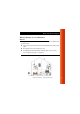
Quick Start - Network Options Stand-Alone Wireless Network This is the out-of-the-box mode of operation for the Residential Gateway-I that allows your client stations to share files and printers. Figure 1-1 Stand-alone Wireless Network Adding wireless computers is as easy as inserting a wireless client adapter and configuring the computer with the same Network Name (page 2-9).
Quick Start - Network Options Wireless Internet Access via Telephone Line The Residential Gateway-I includes a 56K/V90 built-in modem that allows multiple computers to share Internet access. To access the Internet via the Residential Gateway-I modem you will need: ■ An analog telephone line. ■ An ISP (Internet Service Provider) account. ■ View/Modify Residential Gateway-I Settings (page 3-4) to enter the ISP dial-up information to in the Residential Gateway-I.
Quick Start - Network Options Wireless Internet Access via External Devices To access the Internet via an ADSL - PPPoE modem, Cable or ISDN modem you will need to: ■ Connect the external modem to the Residential Gateway-I using a UTP cable. ■ An ISP (Internet Service Provider) account. ■ View/Modify Residential Gateway-I Settings (page 3-4) to enter the correct setting for this type of connection.
Quick Start - Network Options Wireless Internet Access via Ethernet LAN Some companies or educational organizations offer internet access to their employees or students via an existing LAN Infrastructure. In this mode, the Residential Gateway-I tool will: 1-8 ■ Act as a transparent bridge between the wireless and wired network. ■ Disable the integrated DHCP server (i.e. the Residential Gateway-I will no longer assign IP Addresses).
Quick Start - Network Options Residential Gateway-I - Getting Started Guide 1-9
Connect & Power Up 2 Before you start, carefully read the flyer “Information to the User” that is included in your Residential Gateway-I kit. This flyer contains installation requirements and important information about using this product.
Connect & Power Up - Connect Cables Connect Cables 1. Press the latches (a) and remove the cover (b) of the Residential Gateway-I as pictured in Figure 2-1. Figure 2-1 Remove the cover 2. Plug the power connector into the power socket on the Residential Gateway-I unit (see Figure 2-2).
Connect & Power Up - Connect Cables Figure 2-2 Connect Power Adapter 3. Connect the cable for internet access: ■ For Wireless Internet Access via Telephone Line (page 1-8), plug the telephone cable to the correspondent socket (as shown in Figure 2-3) and to the telephone outlet. Depending on local standards, you may need a special adapter plug to connect the cable to the outlet. ■ For Wireless Internet Access via External Devices (page 1-9), plug in the UTP/Ethernet cable into the ethernet socket.
Connect & Power Up - Connect Cables Figure 2-3 Connect Telephone Cable NOTE: Telephone adapter plugs and Ethernet cable are not included, but are available at your local computer dealer. See Interfaces (built-in) (page A-3) for information about cable/connector types. 4. Close the cover by attaching it to the unit, pressing the latches as pictured in Figure 2-4.
Connect & Power Up - Connect Cables Figure 2-4 Close the Unit 5. Place the unit on a flat surface and route the cables through the cable entrance as shown in Figure 2-5.
Connect & Power Up - Power-up the Unit Power-up the Unit 1. Plug the power adapter into an AC power outlet. ! WARNING: After applying power to the Residential Gateway-I, do not cover the unit or block the airflow to the unit with any other objects. Figure 2-6 Residential Gateway-I LEDs 2. Monitor the LED activity on the unit. The LEDs (see Figure 2-6) will change color in the range Yellow, Red and Green to indicate start-up diagnostics.
Connect & Power Up - Power-up the Unit Table 2-7 Icon LED Activity Table - Normal Operation Name Color/Activity Description Power Steady Green Power enabled Wireless Flashing Green Wireless activity between Residential Gateway-I and wireless stations. See also: Stand-Alone Wireless Network (page 1-7). Off Ethernet No communication. Flashing Green Communication between Residential Gateway-I and the wired Ethernet equipment See also: Wireless Internet Access via External Devices (page 1-9).
NOTE: If the Residential Gateway-I does not switch to normal operation within one minute, consult the section Finding Information (page 3-6). 3. Now proceed with the installation of software as described in the Quick Start Overview (page 1-1).
Connect & Power Up - Network Name Network Name The Network Name is the unique 6-character identification code of your wireless network. It is printed on the label, at the bottom of your Residential Gateway-I. Figure 2-8 Label with Network Name (example) In earlier versions of the Residential Gateway-I devices, the Network Name is also referred to as RG ID. The last 5 characters of the Network Name also match the default data encryption key.
Customize the Residential Gateway-I settings 3 Introduction When you have installed the Wireless LAN network adapters on your computers and set up the Residential Gateway-I, you can start to use your Stand-Alone Wireless Network (page 1-5). To set up your Residential Gateway-I for Internet access, you will need to: 1. Obtain an account with an Internet Service Provider. 2. Start the RG Setup Utility (page 3-2). 3.
Customize the Residential Gateway-I settings - Internet Service Internet Service Provider Information When you obtain an account with the Internet Service Provider (ISP), you will typically receive the following information: ■ Telephone numbers to dial in to your ISP Wireless Internet Access via Telephone Line (page 1-6) option. ■ Account Name (or User Name). ■ Account Password (or User Password).
Customize the Residential Gateway-I settings - Internet Service ■ View/Modify the settings of the wireless adapter in your computer to ensure that: — The Network Name matches the value printed on the label at the bottom and at the back of unit. Please note that the alphabetical characters are case-sensitive. — ■ The encryption key matches the value of the Residential Gateway-I (default key matches the last five digits of the Network Name).
Customize the Residential Gateway-I settings - View/Modify Residential View/Modify Residential Gateway-I Settings The RG Setup Utility allows you to view or modify the following network settings: ■ Internet Access Settings (page 3-4) ■ Wireless Connection Settings (page 3-4) Internet Access Settings To setup your Residential Gateway-I for Internet access you will need information from your Internet Service Provider (ISP), such as account name, password, telephone number and/or IP address.
Customize the Residential Gateway-I settings - View/Modify Residential Wireless Channel To transmit and receive data, the Residential Gateway-I uses a frequency channel. If neighboring wireless networks are using the same channel, it is advisable to have your Residential Gateway-I network using a different one. Encryption Key Communication within your network is only possible to wireless computers using the same Encryption Key.
Customize the Residential Gateway-I settings - Finding Information Finding Information The Getting Started Guide provides only basic instructions. For more detailed information: ■ Consult the CD-ROM to view other user documentation. ■ Consult the Online Help that was installed with the software. This Online Help contains detailed instructions, including a troubleshooting section. For context-sensitive help press the Help button on the screens of your RG Setup Utility.
Using your Residential Gateway-I 4 General Guidelines When using your Residential Gateway-I please follow the guidelines listed below: Safety Guidelines ■ Do not cover the unit or block the airflow to the unit. ■ Keep the Residential Gateway-I away from excessive heat and humidity. ■ Keep the unit free from vibration and dust. ■ Always disconnect the Residential Gateway-I power adapter before cleaning.
Using your Residential Gateway-I - General Guidelines ■ The Residential Gateway-I unit can be cleaned with a soft tissue. To avoid damage, do not use aggressive liquids like alcohol or acetone. Do not rinse the unit with fluids. ■ The Residential Gateway-I consumes very little power. In order to extend the life of your Residential Gateway-I it is better to leave the unit powered on. Wall Mount the Residential Gateway-I If you want to mount the Residential Gateway-I to the wall proceed as follows: 1.
Using your Residential Gateway-I - General Guidelines 3. Decide where and how you want to place the Residential Gateway-I (you may consider to mount the unit upside down on high spots, to be able to see the LEDs). 4. Place the cover against the wall, and put three marks on the wall to indicate the screw positions. 5. Use the screws and the plugs that came with your kit to fix the cover to the wall. 6. Close the Residential Gateway-I.
Using your Residential Gateway-I - Residential Gateway-I Buttons Residential Gateway-I Buttons The Residential Gateway-I unit has two small buttons for troubleshooting purposes. ■ Reset button (page 4-5) ■ Reload button (page 4-5) Remove the cover (page 2-2) from the main unit to have access to these buttons as described in “Connect Cables” on page 2-2.
Using your Residential Gateway-I - Residential Gateway-I Buttons Reset button This button allows you to recover from a situation where for some reason the Residential Gateway-I is in a deadlock situation and has the same effect as disconnecting the Residential Gateway-I from the power supply source. After the reset, the Residential Gateway-I will default to the last known configuration profile. ! CAUTION: Pressing the reset button will disable all network communications for a few minutes.
Using your Residential Gateway-I - Residential Gateway-I Buttons For more information, see Finding Information (page 3-6).
Using your Residential Gateway-I - Special modes Residential Special modes Residential Gateway-I Special Residential Gateway-I modes occur: ■ After supplying power to the unit (powering up): The Residential Gateway-I will start and automatically returns to normal operation within one minute time. See: Power-up the Unit (page 2-6) ■ After finishing the RG Setup Utility: The network settings will be sent from your computer to the Residential Gateway-I.
A Specifications Technical Specifications Compatibility IEEE 802.11 Standard for high speed Wireless LANs. Bit Error Rate better than 10-5 Range up to 550 meters (see details on page A-5) Frequency band / Channels 2.4 Ghz.
Specifications - Power Specifications Power Specifications Input Voltage Residential 7 to 15V DC Gateway-I Input Voltage Power Adapter 100 to 240V +/- 10% Power Adapter Types Subject to local standards.
Specifications - Interfaces (built-in) Interfaces (built-in) a Wireless LAN Interface b 56K V.90 Modem RJ-11 connector (female) 1.8 m/ 6ft. cable included. c 10BASE-T Ethernet RJ-45 connector (female) Cable not included. ■ Use cross-over UTP cable to connect the device to external modems.
Specifications - Physical Specifications Physical Specifications A-4 Residential Gateway-I Power Adapter Dimensions (HxWxL) 208x52x155 mm 78x48x75 mm Weight 350 g - Operating Temperature 0 to +40 oC o 0 to +50 oC -20 to +85 oC Storage Temperature -10 to +50 C Humidity max.
Specifications - Radio Specifications Radio Specifications Radio Output Power 15 dBm (nominal) Spreading 11-chip Barker Sequence Environment 11 Mb/s 5.5 Mb/s 2 Mb/s 1 Mb/s Max. range 160 m (525 ft.) 270 m (885 ft.) 400 m (1300 ft.) 550 m (1750 ft.
Regulatory Information Wireless communication is often subject to local radio regulations. Although wireless networking products have been designed for operation in the license-free 2.4 GHz band, local radio regulations may impose a number of limitations to the use of wireless communication equipment. NOTE: Refer to the flyer “Information to the User” for more regulatory information that may apply in your country.