
Use and Care Manual


www.factorybuysdirect.com
160942-01A10
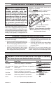
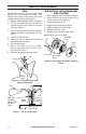
Motor
Shaft
Setscrew
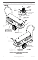
Figure 6 - Fan, Motor Shaft, and
Setscrew Location
Motor
Shaft
Back of Flat on
Motor Shaft
1.82"
Motor
Shaft
Length
Fan
Setscrew
Touching
Back of Flat
on Motor
Shaft
Figure 7 - Fan Cross Section
Fan
Motor
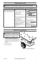
AIR OUTPUT, AIR INTAKE AND
LINT FILTERS
1. Remove upper shell (see Figure 5, page 9).
2. Remove lter end cover screws using
5/16" nut-driver (see Figure 8).
3. Remove lter end cover.
4. Replace air output and lint lters.
5. Wash or replace air intake lter.
6. Replace lter end cover.
7. Replace fan guard and upper shell.
IMPORTANT: Do not oil lters.
Air Intake
Filter
Lint Filter
Filter
End
Cover
Air Output
Filter
Figure 8 - Air Output, Air Intake, and Lint
Filters
SERVICE PROCEDURES
FAN
IMPORTANT: Remove fan from motor shaft
before removing motor from heater. The
weight of the motor resting on the fan could
damage the fan pitch (see Figure 6).
1. Remove upper shell (see Figure 5, page 9).
2. The fan is located with the set screw in
contact with the back of at on motor as
shown in Figure 7.
3. Use 1/8" Allen wrench to loosen setscrew
which holds fan to motor shaft (see Fig-
ure 6).
4. Slip fan off motor shaft.
5. Clean fan using a soft cloth moistened
with kerosene or solvent.
6. Dry fan thoroughly.
7. Place setscrew on flat of shaft.
Tighten setscrew firmly (40-50 inch-
pounds/4.5-5.6 n-m).
8. Replace fan guard and upper shell.