E12 User Manual
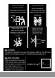
WARNING AVERTISSEMENT ALWAYS FOLLOW SAFETY PRECAUTIONS RESPECTEZ TOUJOURS LES CONSIGNES DE SÉCURITÉ Death or serious injury may occur when children climb on audio and/or video equipment furniture. A remote control or toys placed on the furnishing may encourage a child to climb on the furnishing and as a result the furnishing may tip over on to the child.
Secure the cabinet Only Adults should to avoid fall down. move the cabinet. Sécurisez l’armoire pour L’armoire ne doit être éviterqu’elle soit tombée. déplacé QUE PAR DES Poussée Push Never climb, sit or stand on the cabinet. Personne ne doit s'asseoi r, se tenir ou grimper sur armoire. ADULTES.
CAUTION DO NOT allow anyone to sit, stand or climb on the station. DO NOT lift the station. DO NOT block the ventilation holes used for air circulation. DO NOT overload objects on the station shelves. (shelf maximum loading = 38.1kg / 84lbs). DO NOT put any devices that exceed the maximum loading weight on the shelf of station. DO NOT put any devices (e.g. TV, Monitor, Documents camera, etc.) on top of the station. DO NOT use any TV/monitor/display on top of the station.
Federal Communications Commission Statement NOTE: This equipment has been tested and found to comply with the limits for a Class A digital device, pursuant to part 15 of the FCC Rules. These limits are designed to provide reasonable protection against harmful interference when the equipment is operated in a commercial environment.
Contact Information AVer Information Inc., Americas https://www.averusa.com 668 Mission Ct., Fremont, CA 94539, USA Tel: +1 (408) 263 3828 Toll-free: +1 (877) 528 7824 Technical support: support.usa@aver.
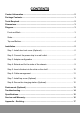
CONTENTS Contact Information ................................................................................................ 5 Package Contents ................................................................................................... 1 Tools Required ........................................................................................................ 2 Dimensions .............................................................................................................. 3 Diagram ...........
Package Contents The following items are included in the package. Please check if each item is available before installing.
Tools Required See the assembly instructions for the tools you’ll need to use Screwdriver (For station use) Drill (For desk mount use) 2
Dimensions Diagram Front and Back 3
Sides Top and Bottom Front and Back Sides Top and Bottom 1. Top cover 6. Power cable hole 13. Ventilation holes 2. Finger pull 7. Ventilation holes 3. Door lock 8. Handle 4. Foot rubber 9. Fix Plate holes 5. Adapter cable holes 10. Snap Rivet holes 11. Ground 12.
Installation Please check that you have taken out all package contents out and the numbers of each item is correct before getting started.
Before installing the charging station 1. Be sure to reserve enough space for installation. It is recommended to reserve at least 47.2”(W)* 35.42”(D) inches. 2. It is recommended to allocate 2 people for efficient assembly. Step 1: Install door lock cover (Optional) First, attach the door lock cover hole on the nut column, and then install the door lock cover using 2 X umbrella head screws into the adapter drawer. 1 2 X2 [Note] It is recommended to use a long screwdriver to tighten screws.
Step 2: Connect the power strip to a wall outlet 1. Remove the packing material of the power strip. 2. Feed the power strip through the hole provided. 3. Connect the power strip to a wall outlet. 1 2 3 [Note] Set the power socket to the OFF position before plugging the charging station to wall outlet.
Step 3: Adapter configuration 1. Place the power adapter onto the adapter drawer in order. 2. Pass the DC-end of the adapter cable through the hole located on the back of the adapter drawer. 3. Plug-in the AC-end of the adapter cable to the power AC socket. 4. Watch your hand when you place the chassis on the adapter drawer. Please make sure the chassis is placed along the edge of the door lock.
Step 4: Extend and fix the sides of the chassis 1. 2. Extend the sides of the chassis out at right angles. Insert 2 x flat head screws and 2 x snap rivets through the hole located on the corners of the rear plate. Each corner has one on the top and one on the bottom (4 screws / snap rivets total). 3. Fix the chassis on the adapter drawer with 3 x flat head screws. [Note] It is recommended to use a long screwdriver to tighten screws. It is recommended to allocate 2 people for efficient assembly.
Step 5: Insert dividers into the slots on the shelf Insert 13 x dividers into the slots on the shelf. Ensure that all dividers are properly seated.
Step 6: Cable management 1. Determine the length of power cable that is needed to reach from the hole located on the back of adapter drawer to the devices. 2. Route the adapter DC-end cable. Along with the V-shape routing groove. 3. Snap the locking piece until hear a "click" to firmly secure the DC-end cable. Remember to reserve enough length of power cable to connect the power plug of the device. 4. Place the mobile device into the bay and plug in the DC-connector to the mobile device.
Step 7: Install top cover (Optional) Place the top cover on the top of both sides. Use 4 x snap rivets on the two outer holes on both sides to prevent removal. [Note] If you insert the snap rivet into the wrong hole, it is recommended to remove it with a scissor and then reinstall with a new snap rivet. Step 8: Secure the charging station (Optional) For security, use the lock key to secure the door.
Desk mount (Optional) 1. Remove the pre-installed screws on the top of cable grommet on each side (See the figure as below for exact locations). 2. Determine the appropriate L- shaped mounting bracket location and fix 2 x L- shaped mounting bracket with screws. 3. Secure the station to the wall studs for drywall mounting. Drill the holes at the wall studs through the drywall, and firmly tap 4 x drywall anchors in until they are flush with the wall. 4.
Troubleshooting Q: Why are all of my devices plugged in but not charging? A: 1. Make sure power cords are undamaged. 2. Make sure power cords are firmly inserted into the available socket with stable current. 3. Make sure the power plug and current consumption are compliant with your country specification standards. Q: My station’s main power cord or station components are damaged.
Specifications Model E12 Capacity 12 Supported Devices Mobile devices up to 15.6" Charging Type Fully Charging Power Specification Power Strip: 100-120V ~ 50/60Hz, 12A Security Door Lock cover: 2 points mechanism with key lock function. Fixed Shelf Yes Shelf Support Weight(ea.) 38.1 kg (84lbs) Adapter Shelves(ea.) 6.
[Note] Supported Devices: please check actual device size, including power cable for compatibility with device compartment size. If in doubt please contact AVer for confirmation. Specifications are subject to change without prior notice. Service and Warranty All of our products come with a quality and safety assurance. For customers located in North America, please visit the AVer USA support site for comprehensive RMA, Warranty, and Service information: https://averusa.
Appendix – Earthing [Caution] High touch current, Connect to earth before connecting to supply. (Yellow/Green wire min. 14AWG) [Note] Installation of the protective earthing connection of the socket-outlet by a skilled person. [Attention] Contact à courant élevé, Reliez l’appareil à la terre avant de la connexion à l’alimentation en courant. (Câble jaune/vert min. 14AWG) [Remarque] L’installation du branchement de mise à la terre sécurisée d’une prise de courant par un professionnel qualifié.
V1