
Instruction Manual
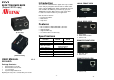

Installation
1. Turn off the PC and monitor.
2. Plug the 5V power supply into the DVI-LD and DVI-R.
3. Turn on the monitor, and connect monitor to the “DVI In”
port on the DVI-LD with DVI cable.
4. Push “EDID COPY” button had completed EDID
read/Write after LED flash 3 times.
5. Remove the monitor cable from the DVI-LD and plug in
the “DVI Out” port
on the DVI-R.
6. Connect the CAT.5 cable between the DVI-LD “CAT.5”
port and the DVI-R “CAT.5” port of extender.
7. Turn on the PC.
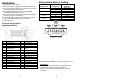
Technical Specifications
Input/Output Signal
Pin # Signal Pin # Signal
1
T.M.D.S Data 2-
16
Hot Plug Detect
2
T.M.D.S Data 2+
17
T.M.D.S Data 0-
3
T.M.D.S Data 2/4 Shield
18
T.M.D.S Data 0+
4
T.M.D.S Data 4-
19
T.M.D.S Data 0/5
Shield
5
T.M.D.S Data 4+
20
T.M.D.S Data 5-
6
DDC Clock
21
T.M.D.S Data 5+
7
DDC Data
22
T.M.D.S Clock Shield
8
Analog Vert. Sync
23
T.M.D.S Clock+
9
T.M.D.S Data 1-
24
T.M.D.S Clock-
10
T.M.D.S Data 1+
11
T.M.D.S Data 1/3 Shield
C1
Analog Red
12
T.M.D.S Data 3-
C2
Analog Green
13
T.M.D.S Data 3+
C3
Analog Blue
14
+5V Power
C4
Analog Horz Sync
15
GND
C5
Analog Ground
-3-
Wiring Information & Coding
Conductor
Identification
RJ45 Pin
Assignment
Color Code for
Conductor
5 White-Blue
Pair 1
4 Blue
1 White-Orange
Pair 2
2 Orange
3 White-Green
Pair 3
6 Green
7 White-Brown
Pair 4
8 Brown
© C&C TECHNIC TAIWAN CO., LTD. All rights reserved.
-4-
Trademarks:
All the companies, brand names, and product names
referred to this manual are the trademarks or
registered trademarks belonging to their respective
companies.