
User guide

PL Series User Manual
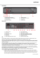
Front Panel
Rear Panel
Operation
Connect speaker cabinets to channel outputs using good quality leads and ensuring that the combined load on each
channel is no lower than 4Ω (for speaker loads connected from one to another, 8Ω + 8Ω = 4Ω).
Connect the left and right signal input from mixer or other line level source via the combo connectors on the rear panel
using good quality 6.3mm jack or XLR leads. If the signal is to be cascaded onto other amplifiers, connect these via the
XLR line level outputs.
Connect the amplifier to the mains outlet, making sure that the IEC lead is in good condition and connected securely.
For extra protection of speakers and amplifier, the CLIP LIMITER may be switched in to help prevent overload.
In some extreme cases, the operation of the clip limiter can be obtrusive. In these cases, disable the clip limiter and use
a dedicated compressor/limiter to control the high dynamics.
If the amplifier is not driving sub cabinets or is driving cabinets which cannot produce very low frequencies, the High
Pass Filters (HPF) may be switched in to avoid excessively low frequencies, which will not be able to be reproduced and
thus dissipate as heat, reducing efficiency. Settings for 30Hz and 50Hz are available.
Select the GAIN level of the input signals (standard is 26dB – may also be used to curtail the input level)
Select the mode in which the amplifier is to be used…
PARALLEL MODE sums both left and right input signals together and feeds the mono signal to both amplifier
outputs. This is useful when driving sub cabinets (which, in arrays, benefit from working together in mono) and
when each channel is powering speakers in different areas (avoiding one area hearing only left output and the
other only right). An LED (“PM”) shows when this mode is engaged
10. PM Parallel Mode indicator 5. SIGNAL indicators
11. BM Bridge Mono mode indicator 6. CH1 and CH2 level controls
12. CLIP indicators 7. Cooling vent
13. OUTPUT indicators 8. POWER switch
9. Mains inlet - IEC 15. CLIP LIMITER switch
10. CH2 output 16. GAIN input level selector
11. Bridge mono output 17. MODE switch (Parallel/Stereo/Bridge)
12. CH1 output 18. CH1 and CH2 High Pass Filters (HPF)
13. Cooling vent 19. GROUND LIFT switch
14. Combo signal inputs (XLR or jack) 20. Signal line outputs (XLR)