
Datasheet

2
Important: For part number identification only, not for
construction of part numbers.
The information below only defines the numerical value of part number
digits, and cannot be used to construct a desired set of electrical limits.
Please refer to the TransGuard
®
part number data for the correct electri-
cal ratings.
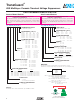
V C 1206 05 D 150 R P
TERMINATION FINISH:
P = Ni/Sn Alloy (Plated)
PACKAGING (Pcs/Reel):
STYLE “D” “R” “T” “W”
VC0402 N/A N/A N/A 10,000
VC0603 1,000 4,000 10,000 N/A
VC0805 1,000 4,000 10,000 N/A
VC1206 1,000 4,000 10,000 N/A
VC1210 1,000 2,000 10,000 N/A
CLAMPING VOLTAGE:
Where: 100 = 12V 500 = 50V
150 = 18V 560 = 60V
200 = 22V 580 = 60V
250 = 27V 620 = 67V
300 = 32V 650 = 67V
390 = 42V 101 = 100V
400 = 42V 121 = 120V
ENERGY:
Where: A = 0.1J J = 1.5J S = 1.9-2.0J
B = 0.2J K = 0.6J T = 0.01J
C = 0.3J L = 0.8J U = 4.0-5.0J
D = 0.4J M = 1.0J V = 0.02J
E = 0.5J N = 1.1J W = 6.0J
F = 0.7J P = 3.0J X = 0.05J
G = 0.9J Q = 1.3J Y = 12.0J
H = 1.2J R = 1.7J Z = 25.0J
WORKING VOLTAGE:
Where: 03 = 3.3 VDC 18 = 18.0 VDC
05 = 5.6 VDC 26 = 26.0 VDC
09 = 9.0 VDC 30 = 30.0 VDC
12 = 12.0 VDC 48 = 48.0 VDC
14 = 14.0 VDC 60 = 60.0 VDC
85 = 85.0 VDC
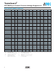
CASE SIZE DESIGNATOR:
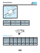
SIZE LENGTH WIDTH
0402 1.00±0.10mm (0.040"±0.004") 0.5±0.10mm (0.020"±0.004")
0603 1.60±0.15mm (0.063"±0.006") 0.8±0.15mm (0.032"±0.006")
0805 2.01±0.2mm (0.079"±0.008") 1.25±0.2mm (0.049"±0.008")
1206 3.20±0.2mm (0.126"±0.008") 1.60±0.2mm (0.063"±0.008")
1210 3.20±0.2mm (0.126"±0.008") 2.49±0.2mm (0.098"±0.008")
CASE STYLE:
C = Chip
G = Chip Glass Encapsulated
PRODUCT DESIGNATOR:
V = Varistor
MARKING:
All standard surface mount TransGuard
®
chips will not be marked.
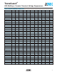
V A 1000 05 D 150 R L
LEAD FINISH:
Copper clad steel, solder coated
PACKAGING (Pcs/Reel):
STYLE “D” “R” “T”
VA1000 1,000 3,000 7,500
VA2000 1,000 2,500 5,000
CLAMPING VOLTAGE:
Where: 100 = 12V 580 = 60V
150 = 18V 650 = 67V
300 = 32V 101 = 100V
400 = 42V 121 = 120V
ENERGY:
Where: A = 0.1J
D = 0.4J
K = 2.0J
WORKING VOLTAGE:
Where: 03 = 3.3 VDC 26 = 26.0 VDC
05 = 5.6 VDC 30 = 30.0 VDC
14 = 14.0 VDC 48 = 48.0 VDC
18 = 18.0 VDC 60 = 60.0 VDC
CASE SIZE DESIGNATOR:
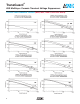
SIZE LENGTH DIAMETER
1000 4.32mm (0.170") 2.54mm (0.100")
2000 4.83mm (0.190") 3.56mm (0.140")
CASE STYLE:
A = Axial
PRODUCT DESIGNATOR:
V = Varistor
MARKING:
All axial TransGuards
®
are marked with vendor identification, product
identification, voltage/energy rating code and date code (see example below):
Where: AVX = Always AVX (Vendor Identification)
TVS = Always TVS (Product Identification
- Transient Voltage Suppressor)
05D = Working VDC and Energy Rating (Joules)
Where: 05 = 5.6 VDC, D = 0.4J
725 = Three Digit Date Code
Where: 8 = Last digit of year (2008)
25 = Week of year
AVX
TVS
05D
825
TransGuard
®
AVX Multilayer Ceramic Transient Voltage Suppressors
PART NUMBER IDENTIFICATION
Surface Mount Devices Axial Leaded Devices
Not RoHS Compliant
LEAD-FREE COMPATIBLE
COMPONENT
For RoHS compliant products,
please select correct termination style.