Notes Please read this user manual carefully to ensure that you can use the device correctly and safely. There may be several technically incorrect places or printing errors in this manual. The updates will be added into the new version of this manual. The contents of this manual are subject to change without notice. This device should be operated only from the type of power source indicated on the marking label. The voltage of the power must be verified before using the same.
Contents ...................................................................................................................................... i 1 Introduction ....................................................................................................................... 1 1.1 1.2 1.3 1.4 1.5 2 Summary ..................................................................................................................... 1 Features ...................................................................
6 PTZ ................................................................................................................................... 37 6.1 PTZ Control Interface Introduction ........................................................................... 37 6.2 Preset Setting ............................................................................................................ 40 6.3 Cruise Setting ......................................................................................................
9.4.2 E-mail ............................................................................................................. 66 9.4.3 Display ........................................................................................................... 66 9.4.4 Buzzer ............................................................................................................ 66 9.5 Manual Alarm ........................................................................................................... 67 9.
Appendix C Compatible Device List ...................................................................................
1 Introduction 1.1 Summary Based on the most advanced SOC technology and embedded system in the field, this series of the NVR adopt the new designed human interface and support the smart management of the IP camera and the record search of slice. This series of the NVR which are powerful and easy to use are provided with excellent image quality and stable system. They are centralized monitoring management products with high performance and high quality specially designed for network video monitoring field.
size Support multiple popular P.T.Z.
Support record to be backed up by time/event/image searching Support record cutting for backing up when playing back Support a maximum of 10 backup tasks in background and backup status viewing Alarm Management Support alarm schedule setting Support enabling or disabling of the motion detection, external sensor alarm input and exception alarms including IP address conflict alarm, disk IO error alarm, disk full alarm, no disk alarm, illegal access alarm, network disconnection alarm, IPC offline a
Support auto recognition of the displayer’s resolution 1.3 Front Panel Descriptions The following descriptions are for reference only.
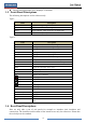
No. Name 1 ALARM OUT Relay output; connect to external alarm 2 GND 3 AUDIO IN 4 DC12V Grounding Audio input; connect to audio input device, like microphone, pickup, etc DC12V power input 5 LAN Network port 6 VGA Connect to monitor 7 ALARM IN Alarm inputs for connecting sensors 8 HDMI Connect to high definition display device 9 USB Connect USB storage device or USB mouse 10 AUDIO OUT Audio output; connect to sound box 11 RS485 Connect to keyboard. A is TX+; B is TX- No.
No. Name Descriptions 6 LAN Network port 7 HDMI Connect to high definition display device 8 USB Connect USB storage device or USB mouse 9 GND Grounding 10 ALARM OUT Relay output; connect to external alarm 11 ALARM IN 12 AUDIO IN 13 Power Switch Alarm inputs for connecting sensors Audio input; connect to audio input device, like microphone, pickup, etc Press the switch to turn on/off the NVR 14 Power Supply Power supply interface No.
No. Name Descriptions 1 Power Supply DC48V power supply interface 2 PoE port 8 PoE network ports; connect to 8 PoE IP cameras 3 LAN Network port 4 VGA Connect to monitor 5 HDMI 6 USB3.0 7 AUDIO IN 8 AUDIO OUT Connect to 1920×1080 high definition display device USB3.0 interface, connect USB storage device or USB mouse Audio input; connect to audio input device, like microphone, pickup, etc Audio output; connect to sound box 9 Power Supply DC12V power supply interface 1.
Alarm Input: Alarm IN 1~16 are 16 CH alarm input interfaces. There are no type requirements for sensors. NO type and NC type are both available. The way to connect sensor and the device is as shown below: The alarm input is an open/closed relay. If the input is not an open/closed relay, please refer to the following connection diagram: Alarm Output: The way to connect alarm output device: Pull out the green terminal blocks and loosen the screws in the alarm-out port.
RS485 Connection There are two types of RS485 interfaces: (Type 1) (Type 2) Type 1: The P/Z interfaces are unavailable temporarily. K/B interfaces are used to connect keyboard. Type 2: The RS485 interfaces are used to connect keyboard. A is TX+; B is TX-.
2 Basic Operation Guide 2.1 Startup & Shutdown Please make sure all the connections are done properly before you power on the unit. Proper startup and shutdown are crucial to expending the life of your device. 2.1.1 Startup ① Connect the output display device to the VGA/HDMI interface of the NVR. ② Connect with the mouse and power. The device will boot and the power LED would turn blue. ③ A WIZARD window will pop up (you should select the display language the first time you use the NVR). Refer to 3.
Button Power Button Function Switch off—to stop the device Record Button To start recording -/-- /0-9 Input number or choose camera Fn1 Button Unavailable temporarily Multi Button To choose multi screen display mode Next Button To switch the live image SEQ To go to sequence view mode Audio To enable audio output in live mode Switch No function temporarily Direction button To move cursor in setup or pan/title PTZ Enter Button To confirm the choice or setup Menu Button To go to menu Ex
Button Function REC Record manually Search To enter search mode MEUN To enter menu Exit To exit the current interface ENTER To confirm the choice or setup Direction button To move cursor in setup ZOOM To zoom in PIP No function temporarily To control playback. Play(Pause)/Next Frame/Speed Up/Stop/Previous Frame/Speed Down Multi To choose multi screen display mode Next To switch the live image SEQ To go to sequence view mode INFO Get information about the device 2.
The system includes two input boxes. Refer to the above pictures. The left box is the number input box and the right box is the input box which provides inputs of numbers, letters and punctuation characters. The introductions of keys on the input boxes are shown below. Button Meaning Button Meaning Backspace key Switch key of punctuation character Delete Key Enter key Switch key between upper and lower letter Space key Switch key of language 2.
3 Wizard & Main Interface 3.1 Startup Wizard The disk icons will be shown on the top of the startup interface. You can view the number and status of each disk quickly and conveniently through these icons ( : no disk; : unavailable disk; : RW available disk). You can quickly configure the NVR by wizard setup to make the NVR work normally. You must configure the wizard if you start the NVR for the first time (or click “Skip” to cancel the wizard next time). Click “Wizard Setup” to start wizard.
② Date and Time Configuration. The date and time of the system need to be set up if you use the wizard for the first time. Refer to the following figure. Set the time zone, system time, date format and time format. The DST will be enabled by default if the time zone selected includes DST. Click “Next” to continue. ③ Network Settings.
Note: If you use the NVR with the PoE network ports, the online state of the internal ethernet port will be shown on the interface. Refer to the picture below. Please refer to 11.1.1 TCP/IPv4 Configuration for detail introduction of the internal ethernet port. ④ QRCode. You can scan the QRCode through mobile client which is installed in the mobile phone or PAD to log in the mobile client instantly. Please refer to 12.1 Mobile Client Surveillance for details. ⑤ Add Camera.
Click to edit the searched IP camera as shown on the below left. Input the new IP address, subnet mask, gateway, username and the password of the camera. Click “OK” to save the settings. Click to edit the added camera as shown on the above right. Input the new camera name, IP address, port, username and the password of the camera. You can click “Test” to test the effectiveness of the input information. Click “OK” to save the settings. You can change the IP camera name only when the added camera is online.
⑦ Record Settings. Two record modes are available: auto and manual. Auto: Select one auto mode in the interface as shown below and then click “OK” button to save the settings. See 7.1.1 Mode Configuration for details. Manual: Set the “Sensor Record”, “Motion Record” and “Schedule Record” of each camera. Click “OK” to save the settings. See 7.1.1 Mode Configuration for details.
3.2 Main Interface 3.2.1 Main Interface Introduction The buttons in area ① are introduced in the table below. Button Meaning Start button. Click it to pop up area ③. Full screen button. Click it to show full screen; click it again to exit the full screen. Screen mode button. Dwell button (see 5.2.2 Quick Sequence View and 5.2.4 Scheme View In Sequence for details). Click it to enable OSD; click to disable OSD. Click to set the default playback time before starting instant playback (8.
Button Meaning Disk status button. Click it to view the disk status and RAID status. Network status button. Click it to view the network status. Information button. Click it to view system information. Introduction of area ②: Click “Camera” to view all the added cameras in the camera list. Select one camera window on the left side of the interface and then double click one camera in the list to preview the camera image in the selected window.
The setup panel includes seven modules. Each module provides some function entries with links for convenient operation. Here we take Camera module as an example. The Camera module provides convenient links such as “Add Camera”, “Edit Camera”, “Image Settings”, “Motion” and “PTZ”. Click Camera to go to the camera management interface as shown below. There are some function items on the left side of the camera management interface. Click each item to go to corresponding interface or window.
Click the main menus on the top of the camera management interface to go to corresponding interfaces. Refer to the picture below. For instance, you can go to system setup interface by clicking “System” tag. 3.2.3 Main Functions Camera The module covers the functions such as Camera Management (see Chapter 4 Camera Management for details), Image Settings (see 5.3 Preview Image Configuration for details), Motion (see 9.2.
and so on. Please see 11.1 Network Configuration for details. Account and Authority The module covers the functions such as Account Management (see 10.1 Account Management for details) and Permission Management (see 10.3 Permission Management for details) and so on. System The module covers the functions such as Basic Configuration (see 11.2 Basic Configuration for details), Device Information (see 11.7 View System Information for details), Log Information (see 11.
4 Camera Management 4.1 Add/Edit Camera 4.1.1 Add Camera The network of the NVR should be set before adding IP camera (see 11.1.1 TCP/IPv4 Configuration for details). Refer to the pictures below. Click Add Camera in the setup panel or in the top right corner of the preview window to pop up the “Add Camera” window as shown below. You can quickly add or add the IP camera manually. Quickly Add Check the cameras and then click “Add” to add cameras.
Add Manually Input the IP address, port, username and password of the camera and then select the protocol. Click “Test” to test the effectiveness of the input information and then click “Add” button (you can input one camera’s information or above such as IP address, username and password before clicking “Add” button). Click to delete the camera. Click “Default Password” to set the default username and password of each camera. 4.1.
The IP camera which directly connects to the PoE port of the NVR through private protocol will be shown automatically in the camera list. One of the two conditions must be met if the IP camera which directly connects to the PoE port of the NVR through ONVIF protocol should be shown automatically in the camera list. The IP camera which directly connects to the PoE port is in the same network segment with the internal ethernet port.
Click to pop up the window as shown below. Set the group name and dwell time (the dwell time of the camera group sequence view) in the window. Check the cameras and then click “Add” to add group. Click to view the cameras in the group after adding group. 4.2.2 Edit Camera Group Click to modify the group information such as group name and dwell time. Click to delete the group.
5 Live Preview Introduction 5.1 Preview Interface Introduction You should add camera first after logging on to the system (see 4.1.1 Add Camera for details). Refer to the interface as shown below, drag one camera in the preview window to another window for camera window exchanging. Click the preview window to show the tool bar as shown in area ①; right click the preview window to show the menu list. The tool bar and menu list are introduced in the table below. Button -- Menu List Meaning -- Move tool.
The single channel amplification interface is as shown below. Press and drag the blue box to select the zoom in area. Click / to zoom the image. Click the camera selection box to select other cameras for amplification. Click “Back” to return to the live preview interface. 5.2 Preview Mode 5.2.1 Preview By Display Mode Set different screen modes and cameras’ display sequences as required and then save the display modes classified by surveillance areas, priorities and so on. Refer to the picture below.
Add Display Mode Method One: ① Click “Customize Display Modes” in the above interface and then set the screen mode. ② Add the cameras and adjust the cameras’ display sequence as required. ③ Click “Save” button under the display mode list and then enter the display mode name in the popup window, click “OK” button to save the current display mode. Method Two: ① Click StartSettingsSystemBasicOutput Settings to go to the interface and then set the screen mode.
camera number of the current screen mode. Double click the sequence view interface to pause the view; double click again to restore the view. Click to stop the view. 5.2.3 Camera Group View In Sequence You can start camera group view in sequence if camera group has been created (see 4.2.1 Add Camera Group for details). ① Go to the live preview interface and then select a camera window. ② Double click one camera group on the right side of the interface.
Add Scheme Click in area ① to create a new scheme. Click scheme to delete it. on the top right corner of the Configure Scheme a) Select a scheme in area ① and then click the screen mode button on the tool bar to set the screen mode of the scheme. b) Select a camera window in area ② and then double click the camera or group in area ③. The camera or group will be added into the selected window. One camera in the same scheme cannot repeat.
5.3.2 Image Settings Click StartSettingsCameraImageImage Settings to go to the following interface. Select the camera and then set the brightness, contrast, saturation and hue of the camera. You can click “Default” button to restore the image settings to the default factory settings. 5.3.3 Mask Settings Some areas of the image can be masked for privacy. Up to four mask areas can be set for each camera. Click StartSettingsCameraImageMask Settings to go to the interface as shown below.
5.3.4 Image Adjustment Go to live preview interface and then click window to go to the image adjustment interface. button on the tool bar under the camera Image Adjustment Select the camera and then click “Image Adjustment” to go to image adjustment tab. Refer to the above picture. Drag the slider to set the camera’s brightness, contrast, saturation and hue value. Check sharpen, wide dynamic and denoise and then drag the slider to set the value.
The introductions of these parameters are as follows: Parameter Meaning Brightness It is the brightness level of the camera’s image. Contrast It is the color difference between the brightest and darkest parts. Saturation It is the degree of color purity. The color is purer, the image is brighter. Hue It relates to the total color degree of the image. Sharpen It relates to the resolution level of the image plane and the sharpness level of the image edge.
The introductions of these parameters and buttons are as follows: Button/Parameter Meaning Click Focus Mode / to zoom in/out the image. If manual mode is selected, focus button & “One Key Focus” & “Day/night mode switch autofocus” will be available; if auto mode is selected, the time interval setup will be available. Click / to increase/decrease the focal length. Click it to focus instantly.
6 PTZ 6.1 PTZ Control Interface Introduction You can control the IP dome or PTZ which connects to the IP camera for PTZ control. Click on the tool bar at the bottom of the live preview window to go to the PTZ control interface as shown below. You can select another IP dome or PTZ which connects to the IP camera on the top right of the interface for PTZ control. Introductions of the buttons on the bottom right of the interface: Button Meaning Click / / / to rotate the dome.
Analog Joystick Control The analog joystick on the left side of the interface provides quick PTZ control. The dome or PTZ will rotate when you drag the analog joystick. The farther you drag the analog joystick from the middle of the image, the faster the dome or PTZ rotates. The dome or PTZ will stop rotating when you stop dragging the analog joystick. 3D Control Click the camera image on any area and then the image will be centered on the clicked point. Refer to the picture as shown below.
Advanced 3D Control Double click the left button of the mouse on any area of the camera image and then the image size will be doubled and centered on the clicked point. Press and hold the left button of the mouse on any area of the camera image to zoom in the image; press and hold the right button to zoom out the image.
adjusting the dome’s direction); click in the preset list to call the preset; click “Delete” button to delete the selected preset. You can also go to preset setting interface for preset setting, see 6.2 Preset Setting for details. Cruise Setting Click “Cruise” to go to cruise operation tab and then click “Add” button to pop up a window as shown below left. You can add 8 cruises for each dome at most.
Add preset Select camera and then click “Add” button to add preset; or click in the camera list on the right side of the interface to display the preset information of the dome and then click to add preset. The operations of the “Add Preset” window are similar to that of the PTZ control interface; please see 6.1 PTZ Control Interface Introduction for details. Edit preset Select camera and preset. You can input the new name of the preset and then click to save the new preset name.
Add Cruise Click in the camera list on the right side of the interface to display the cruise information of the dome and then click to add cruise. The operations of the “Add Cruise” window are similar to that of the PTZ control interface; please see 6.1 PTZ Control Interface Introduction for details. Edit Cruise Select the camera and cruise in the “Cruise” interface. Input the new cruise name and then click to save the cruise name. Click “Add Preset” to add preset to the cruise.
7 Record & Disk Management 7.1 Record Configuration 7.1.1 Mode Configuration Please format the HDDs before recording (refer to 7.5 Disk Management for details). Click StartSettingsRecordMode Settings to go to the mode settings interface. You can set the record time under the “Manual Record Settings” and then click “Apply” button to save the settings. There are two record modes: auto mode and manual mode. Auto Mode Motion Record: Motion alarm record will be enabled when motion alarm happens.
Video Encode: the available options will be H.265 and H.264 if the connected IP camera supports H.265, or the option will be H.264 only. Resolution: the higher the resolution is, the clearer the image is. FPS: the higher the frame rate is, the more fluency the video is. However, more storage room will be taken up. Bitrate: the higher the image quality you choose, the more bit rate will be required.
7.2 Encode Parameters Setting Click StartSettingsRecordEncode Parameters to go to the interface as shown below. Set the video encode, resolution, FPS, bitrate and audio of main stream for each camera in “Event Record Stream” and “Timing Record Stream” interfaces. Click “Apply” to save the settings. You can set the record stream of each camera one by one or batch set them for all cameras. Click StartSettingsRecordStream Settings to go to “Sub-stream” interface.
Click to add a new schedule. Refer to the picture below.
Set the schedule name and schedule time and then click “Add” to save the schedule. You can set day schedule or week schedule. : add button; : delete button. Set Day Schedule Click and then drag the cursor on the time scale to set record time; click and then drag the cursor on the time scale to delete the selected area. You can manually set the record start time and end time. Click or and then click “Manual” on each day to pop up a window as shown below.
Click “All” to set all week recording; click “Reverse” to swap the selected and unselected time in a week; click “Clear All” to clear all the selected area in a week. 7.3.2 Record Schedule Configuration Click StartSettingsRecordRecord ScheduleSchedule Configuration to go to the interface as shown below. Set the schedule of sensor record, motion record and timed record. Click “None” in the drop-down menu to clear the schedule. Click “Apply” to save the settings.
7.4.2 Timing Recording Timing Recording: the system will record automatically according to the schedule. Set the timing record schedule of each camera. See 7.3 Schedule Setting for details. 7.4.3 Motion Based Recording Motion Based Recording: the system will start motion based recording when the motion object appears in the setup schedule. The setup steps are as follows: ① Set the motion based recording schedule of each camera. See 7.3 Schedule Setting for details.
There are all four disk groups. By using disk group, you can correspond the camera to disk (the record data of the camera in the group will be stored into the disks in the same group). The added disks and cameras will be added into group one automatically. The disks and cameras in the groups can be deleted except group one (select a disk group and then click on the top right corner of the added disk or camera to delete it from the group).
51
8 Playback & Backup 8.1 Instant Playback Click on the tool bar at the bottom of the preview camera window to play back the record (click on the tool bar at the bottom of the live preview interface to set the default playback time). Refer to the picture below. Drag the playback progress bar to change the playback time. You can also click the right-click menu “Instant Playback” in the camera window and then set the instant playback time to play back the record. 8.
The added cameras will playback their records in the playback interface automatically. You can also add the playback camera manually. Click in the playback window to pop up the “Add Camera” window. Check the cameras in the window and then click “Add” to add playback camera. The system supports a maximum of 16 synchronous playback cameras. The buttons on the tool bar (area ①) at the bottom of the playback interface are introduced in the table below. Button Meaning Start button. Click it to pop up area ②.
Click on the playback window to show the tool bar as shown in area ③; right click on the window to show the menu list. The tool bar and menu list are introduced in the table below. Button Menu List Meaning -- Move tool. Click it to move the tool bar anywhere. Enable Audio Click it to enable audio. You can listen to the camera audio by enabling audio. Snap Click it to snap. Click it to go to the zoom in interface.
pop up the backup window. Select the device, backup path and backup format and then click “Backup” button to start the backup. 8.3 Record Search & Playback 8.3.1 Search & Playback by Time-sliced Image ① Click StartSearchBy Time-sliced Image to go to “By Time-sliced Image” tab. There are two view modes: by time and by camera. In the time view mode, a maximum of 64 camera thumbnails can be showed.
Time Slice Mode Selecting: Method One: Click “Year”, “Month” or “Day” button under the record time scale to select the time slice mode. In “Day” mode, click / on the left/right side of the time scale to view the record of the last/next day; click “Minute” in the “Picture” option under the time scale to select “Minute” mode (in “Minute” mode, click the time scale to change the time of the 60 display windows) and click “Hour” to select “Hour” mode.
8.3.3 Search & Playback by Event ① Click StartSearchBy Event to go to “By Event” tab as shown below. ② Check the event type in the interface as required. ③ Click to set the start time and end time on the top left of the interface. ④ Check cameras on the left side of the interface and then click to search the record. The searched record will be displayed in the list.
⑤ Click in the list to play back the record in the popup window. Select one record data in the list and then click “Backup” button for record backup. ⑥ Select one record data in the list and then click “Playback” button to play the record in the playback interface. 8.3.4 Search & Playback by Tag Only if you add the tags can you play the record by tag search.
④ Click “Backup” button to pop up the “Record Backup” window as shown below. Select the device name, backup format and path and then click “Backup” button to start the backup. Note: If you back up the record in private format, the system will back up a RPAS player to USB device automatically. The private format record can be played by RPAS player only. 8.4.2 Backup by Event ① Click StartBackupBy Event to go to “By Event” tab.
② Click to set the start time and end time on the left top of the interface. ③ Check the event types and cameras. ④ Click to search the record. The searched record data will be displayed in the list. Click in the list to play the record in the small popup playback window. Click to back up the record. Check one record data or above in the list and then click “Backup” button to back up the record data. 8.4.3 Image Management Click StartBackupImage Management to go to “Image Management” tab.
8.4.4 View Backup Status Click StartBackupBackup Status or click playback interface to view the backup status.
9 Alarm Management 9.1 Sensor Alarm To complete the entire sensor alarm settings, you should enable the sensor alarm of each camera and then set up the alarm handling of each camera. ① Click StartSettingsAlarmSensor Alarm to go to the following interface. ② Select the alarm type (NO or NC) according to trigger type of the sensor. ③ Enable the sensor alarm of each camera.
Pop-up Message Box: if enabled, the system will pop up the corresponding alarm message box automatically when the sensor alarm is triggered. To set the duration time of the message box, please see 9.4.3 Display for details. E-mail: if enabled, the system will send an e-mail when the sensor alarm is triggered. Before you enable the email, please configure the recipient’s e-mail address first (see 11.1.4 E-mail Configuration for details). 9.
③ Drag the camera image to set the motion area. You can set more than one motion area. Click “All” to set the whole camera image as the motion area. Click “Reverse” to swap the motion area and the non-motion area. Click “Clear” to clear all the motion areas. ④ Click “Apply” to save the settings. Click “Processing Mode” to go to the alarm handling configuration interface of the motion alarm. 9.2.2 Motion Alarm Handling Configuration ① Click StartSettingsAlarmMotion Alarm to go to the following interface.
9.3.2 IPC Offline Settings ① Click StartSettingsAlarmExceptionIPC Offline Settings to go to the interface as shown below. ② Enable or disable “Snap”, “Alarm-out”, “Preset”, “Buzzer”, “Pop-up Video”, “Pop-up Message Box” and “E-mail”. The IPC Offline Settings are similar to that of the sensor alarm (see 9.1 Sensor Alarm for details). ③ Click “Apply” to save the settings. 9.4 Alarm Event Notification 9.4.1 Alarm-out ① Click StartSettingsAlarmEvent Notification to go to the following interface.
② Set the delay time and the schedule of each alarm-out. You can click “Edit Schedules” to edit the schedules (see 7.3.1 Add Schedule for details). ③ Click “Apply” to save the settings. You can click “Test” to test the alarm output. 9.4.2 E-mail Click StartSettingsAlarmEvent NotificationE-mail to go to the e-mail configuration interface. Set the e-mail address of the recipients. See 11.1.4 E-mail Configuration for details. 9.4.
9.5 Manual Alarm Click on the tool bar at the bottom of the live preview interface to pop up a window. Click “Trigger” to start alarm. Click “Clear” to stop alarm. 9.6 View Alarm Status Click StartSettingsAlarmAlarm Status or click live preview interface to view the alarm status. on the tool bar at the bottom of the Click “Clear” button to stop the buzzer when the buzzer alarm happens. Click the detail information as shown below.
If the exception information is more than one page, you can input the number in the box and then click to jump to the specified page. Click / to view the exception alarm information in the previous/next page. Click to play the alarm record.
10 Account & Permission Management 10.1 Account Management Click StartSettingsAccount and AuthorityAccountEdit User to go to the interface as shown below. Area ① displays the user permissions. Area ② displays the user list. Click the user in the list to display its user permissions in area ①. There are three default permission groups (“Administrator”, “Advanced” and “Ordinary”) available when adding accounts. You can manually add new permission group (see 10.3.1 Add Permission Group for details).
② Set the username, password and group. The e-mail address, MAC address and the remark are optional (input the MAC address after you check it). Click “Add” to add the user. 10.1.2 Edit User Click StartSettingsAccount and AuthorityAccountEdit User and then click in the user list or double click the user to edit the user information. Click to delete the user (the user admin cannot be deleted). Edit Security Question You can set password security only for admin.
Edit User Click “Edit User” to pop up the window as shown below. The admin is enabled, its permission control is closed and permission group cannot be changed by default. You can enable or disable other users (if disabled, the user will be invalid), open or close their permission control (if closed, the user will get all the permissions which the administrator permission group has) and set their permission groups. Click “OK” to save the settings. 10.
Click to add permission group. Set the group name, check the permissions as required and then set the “Local” and “Remote” permissions. Click “Add” to save the settings.
10.3.2 Edit Permission Group Go to “Edit Permission Group” interface and then click in the group list to edit the permission group (the operations of the “Edit Permission Group” are similar to that of the “Add Permission Group”, please see 10.3.1 Add Permission Group for details). Click to save the group as another group. Click to delete the permission group. The three default permission groups (“Administrator”, “Advanced” and “Ordinary”) cannot be deleted. 10.
11 Device Management 11.1 Network Configuration 11.1.1 TCP/IPv4 Configuration IP Address Settings Click StartSettingsNetworkTCP/IPv4 to go to the following interface. Check “Obtain an IP address automatically” and “Obtain DNS automatically” to get the IP address and DNS automatically, or manually input IP address, subnet mask, gateway, preferred DNS and alternate DNS. Click “Apply” to save the settings.
segment with the IP cameras which directly connect to the PoE ports of the NVR (it is not recommended to change the IP address and subnet mask of the internal ethernet port). PPPoE Settings In the above interface, check “Enable” in “PPPoE Settings” and then input the username and password obtained from the dealer. Click “Apply” to save the settings. 11.1.2 Port Configuration Click StartSettingsNetworkPort to go to the interface as shown below.
through IE, you should input IP address plus HTTP port in the IE address bar like http://192.168.11.61:81. Server Port: the default server port of the NVR is 6036. The server port number can be changed as required. The port is mainly used in network video management system. RTSP Port: RTSP real-time stream protocol can be used to control the sending of real-time data. By media player which supports the RTSP real-time stream protocol, you can view the live images synchronously.
② Click Registration button to go to the interface as shown below. Set the DDNS account information (username, password and so on) and then click Submit button to save the account. ③ Create domain name and then click Request Domain.
④ After you successfully request your domain name, you will see your domain name information in the list. ⑤ Click StartSettingsNetworkDDNS to go to DDNS setting interface. Enable DDNS and then select the www.dvrdydns.com DDNS type. Input the registered username, password and domain name and then click “Apply”. ⑥ Map the IP address and HTTP port in the router (you can skip this step if UPnP function is enabled). ⑦ Input the registered domain name plus HTTP port like http://www.xxx.dvrdydns.
Click “Edit Recipient” to go to the following interface. Click “Add” and then input the recipient’s e-mail address in the popup window. Click “Add” in the window to add the recipient. Click to delete the recipient in the list. Click “Apply” to save the settings. Click “Edit Sender” to go to the e-mail configuration interface of the sender. 11.1.5 UPnP Configuration By UPnP you can access the NVR through IE client which is in WAN via router without port mapping.
③ Set the NVR’s IP address, subnet mask and gateway and so on corresponding to the router. ④ Check “Enable” in the interface as shown below and then click “Apply” button. Click “Refresh” button to refresh the UPnP status. If the UPnP status were still “Invalid UPnP” after refreshing it for many times, the port number would be wrong. Please change the mapping type to “Manual” and then click to modify the port until the UPnP status turns to “Valid UPnP”. Refer to the following picture.
Device Name: The name of the device. It may display on the client end or CMS that help user to recognize the device remotely. Video Format: Two modes: PAL and NTSC. Select the video format according to the camera. 11.2.2 Date and Time Configuration Click StartSettingsSystemBasicDate and Time to go to the interface as shown below. Set the system time, date format, time format and time zone of the NVR. The default time zone is GMT+08 Beijing, Hong Kong, Shanghai, Taipei.
11.3 Factory Default Click StartSettingsSystemMaintenanceFactory Default and then click “Reset to factory default” button in the interface to reset to the factory default settings. 11.4 Device Software Upgrade You can click StartSettingsSystemInformationBasic to view MCU, kernel version and firmware version and so on. Before upgrade, please get the upgrade file from your dealer. The upgrade steps are as follows: ① Copy the upgrade software into the USB storage device.
Insert the USB storage device into the USB interface of the NVR and then click StartSettingsSystemMaintenanceBackup and Restore to go to the interface. Backup Select the USB device in “Device Name” option; go to the path where you want to store the configuration backup file and then click “Backup” button; finally click “OK” button in the popup window.
12 Remote Surveillance 12.1 Mobile Client Surveillance ① Enable NAT in the NVR. Refer to 11.1.6 NAT Configuration for details. ② Download and install the mobile client “SuperLive Plus” into the mobile device with the Android or iOS system. ③ Run the mobile client, go to the “Add Device” interface and then click to scan the QRCode of the NVR (Go to StartSettingsSystemInformationBasic to view the QRCode of the NVR).
Notes: 1. Please make sure that the IP address of the NVR and the computer are both in the same local network segment. For example, supposing that the IP address of the computer is 192.168.1.41, the IP address of the NVR shall be set to 192.168.1.XXX. 2. If the HTTP port of the NVR is not 80, but other number instead, you need to input the IP address plus port number in the IE address bar when accessing the NVR over network. For example, the HTTP port is 81. You should enter http://192.168.1.
Input the serial number (click on the tool bar at the bottom of the live preview interface to see the serial number of the NVR), user name (the user name of the NVR, admin by default) and password (the password of the NVR, 123456 by default) of the NVR, select the display language on the top right corner of the interface and then click “Login” button to go to the web client interface. PPPoE Access ① Click StartSettingsNetworkTCP/IPv4 to go to the “TCP/IPv4” interface.
admin: the current login username. Logout: click it to log out and return to the login interface. Modify Password: click it to change the password of the current login user. Input current password and then set a new password in the popup window. Click “OK” button to save the new password. Local Settings: click it to change the local settings. Set the snapshot number and click “Browse” to set the snapshot path and record path as shown below. Click “Apply” button to save the settings. 12.4.
Left Panel Introduction Click on the left panel to hide the panel and click all the added cameras and groups on the left panel. to show the panel. You can view View Camera Click to view the cameras. You can view the number of all the added cameras and the online cameras. For instance, the left number 3 in on the left panel stands for the number of online cameras; the right number 4 stands for the number of all the added cameras.
Click one camera window in the preview area and then click to set the camera’s live preview stream and record stream to main stream in manual record mode; click to set the camera’s live preview stream and record stream to sub stream. In sub stream tab, set the resolution, FPS and bitrate and then click “Apply” to save the settings. Operation panel introduction: Button Meaning Click it to snap. Click it to start recording; click it again to stop recording.
PTZ panel introduction: Button Meaning Click / / / to rotate the dome; click / / / / to stop rotating the dome. Drag the slider to adjust the rotating speed of dome. Click / to zoom in/out camera image. Click / to increase/ decrease the focal length. Click / to increase/decrease the iris of the dome. Click it to view the preset list and then click the button in the list to call the preset.
Button Meaning Backup tasks button. Click it to view the backup status. Event list button. Click it to view the event record of manual/schedule/sensor/motion. 12.4.3 Remote Backup Click “Backup” in the remote interface to go to the backup interface. You can back up the record by event or by time.
Appendix A FAQ Q1. Why can’t I find the HDD? a. Please check the power and SATA data cables of the HDD to make sure they are well connected. b. For some NVRs with the 1U or small 1U case, the power of the adapter may be not enough for operating them. Please use the power adaptor supplied along with the NVR. c. Please make sure the HDDs are compatible with the NVR. See Appendix C Compatible Device List for details. d. The HDD could have gone bad. Change a new one. Q2.
Q6. The IP camera which connects to the PoE port of the NVR cannot be displayed automatically in the camera list, why? a. Please check whether the resource of the PoE port is occupied by another IP camera that is added through network. Take the 16 CH NVR with 8 PoE ports as an example. The resource distribution of the 16 CH IP cameras is shown in the picture below.
b. Please make sure that the internal ethernet port and the IP camera which directly connects to the PoE port through ONVIF protocol are in the same network segment. The internal ethernet port and the IP camera which directly connects to the PoE port through ONVIF protocol should be in the same network segment, or you will fail to add the IP camera.
Q8. The system cannot record, why? a. Make sure the HDD was formatted prior to use. b. The record schedule has not been set in manual record mode. Please refer to 7.3.2 Record Schedule Configuration for details. c. Maybe HDD is full and thus the NVR is not able to record. Check HDD information from Disk Management and if required, please enable the recycle function (please see 7.1.2 Advanced Configuration for details). d.
b. Other plug-ins or anti-virus may block ActiveX. Please disable or do the required settings. Fig 10-1 Q11. Fig 10-2 How to play the backup file? a. Record backed up by NVR: insert the USB device in which the record backup files is saved to the USB interface of the PC and then open the USB device path. The record can be backed up in the private format and AVI format by NVR.
Fig 11-1 Fig 11-2 97
Appendix B Calculate Recording Capacity The recording capacity is mainly up to the record resolution, record stream and bitrate. Different image quality parameters decide different disk capacity occupation in equal times. The bigger the record resolution, record stream and record bitrate is, the more disk capacity is taken up in equal times. The calculation format of recording capacity is shown as below.
Appendix C Compatible Device List Compatible HDD list Brand and Series Seagate Western Digital Capacity Barracuda Series 500GB /1TB /2TB /3TB SV35 Series (recommended) 1TB /2TB /3TB Surveillance HDD Series (recommended) 1TB /2TB /3TB /4TB /6TB Blue Series 500GB /1TB Green Series 2TB /3TB /4TB Purple Series (recommended) 1TB /2TB /3TB /4TB /6TB Compatible USB mobile device Brand Capacity SSK 2GB Netac 4GB Kingston 2GB/8GB/16GB/32GB Aigo 2GB Smatter vider 1GB SanDisk 4GB/8GB/16GB