USER MANUAL 1.
Copyright © Berghof Automation GmbH Reproduction and duplication of this document and utilisation and communication of its content is prohibited, unless with our express permission. All rights reserved. Damages will be payable in case of infringement. Disclaimer The content of this publication was checked for compliance with the hardware and software described. However, discrepancies may arise, therefore no liability is assumed regarding complete compliance.
USER MANUAL 1.4 | EC1000 Update Version Date Subject 1.01 25.09.2012 First Version 1.1 31.10.2012 Update of chapter ‚Product description, Block diagram’ 1.2 09.11.2012 Update of the trademarks 1.3 06.02.2013 Update of chapter ‚Annex, Nameplate’ and ‚Annex, Addresses’ Transition into new CD Update of the title page Update of chapter ‚Product description, Module view and pin assignment’ Update of chapter ‚Product description, Technical data’ and ‚Product description, Identification’ 1.4 20.
USER MANUAL 1.4 | EC1000 Blank page 4 Berghof Automation GmbH | Harretstrasse 1 | 72800 Eningen | www.berghof.com EC1000_HB_en_2D1652005ZD00.
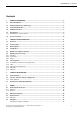
USER MANUAL 1.4 | EC1000 Contents 1. GENERAL INFORMATION ............................................................................................................ 7 1.1. About This Manual ....................................................................................................................... 7 1.2. Hazard Categories and Terminology ........................................................................................... 8 1.3. Conformity Declaration ..............................
USER MANUAL 1.4 | EC1000 4.5. Addresses and Bibliography / Standards .................................................................................. 31 4.5.1. Addresses .................................................................................................................................... 31 4.5.2. Bibliography / Standards...............................................................................................................
USER MANUAL 1.4 | EC1000 1. General Information Documentation This equipment manual is intended for qualified personnel and contains information regarding mounting, installation, commissioning and maintenance. The information contained in this manual is subject to change without prior notice. 1.1. About This Manual This equipment manual is an integral part of the product. Make sure the equipment manual is always available near the product’s point-of-employment.
USER MANUAL 1.4 | EC1000 1.2. Hazard Categories and Terminology The indications described below are used in connection with safety instructions you will need to observe for your own personal safety and the avoidance of damage to property. The indications have the following meaning: DANGER Immediate danger. Failure to observe the information indicated by this warning will result in death, serious injury or extensive property damage. WARNING Potential danger.
USER MANUAL 1.4 | EC1000 1.4. Qualified Personnel Only qualified personnel may install, operate and maintain the controller module. Within the context of this documentation and the safety information it contains, qualified personnel constitutes trained specialists who have the authority to mount, install, commission, ground and identify equipment, systems and power circuits in accordance with the standards of safety technology, and who are familiar with the safety concepts of automation technology. 1.5.
USER MANUAL 1.4 | EC1000 1.6. Use as Prescribed This is a modular automation system based on the CANbus, intended for industrial control applications within the medium to high performance range. The automation system is designed for use within Overvoltage Category I (IEC 364-4-443) for the controlling and regulating of machinery and industrial processes in low-voltage installations in which the rated supply voltage does not exceed 1,000 VAC (50/60 Hz) or 1,500 VDC.
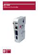
USER MANUAL 1.4 | EC1000 2. Product description EC1000 2.1. Overview The EC1000 is a CODESYS PLC controller with a broad range of data interfaces. In compliance with IEC 61131-3 the module can be programmed either with version 2.3 or 3.x. Brief description Installation The EC1000 is designed for installation in switching cabinets on a DIN mounting rail in a rough industrial environment. The fanless design and the flash memory make the cost and effort for maintenance minimal.
USER MANUAL 1.4 | EC1000 Performance features – an overview 400 MHz CPU User program and data memory (RAM): 128 MB on board, max. 96 MB for application User program memory (Flash): 64 MB on board / 56 MB for CODESYS V2.3 resp. 40 MB for CODESYS V3 application Retain memory, 24 kB 1 Ethernet 10/100 base T interface 1 USB Host interface V1.1 1 CAN interface at the front 1 RS232 serial interface for programming tools and application 1 EtherCAT interface with up to 10 users (or max.
USER MANUAL 1.4 | EC1000 2.2. Technical data Ethernet Controller EC1000 Module data Designation EC1000 MP400 00 1131 EC1000 MP400 00 1131 V3 Item no. 204900000 204900100 Programming tool CODESYS V2.3 At least CODESYS V3.5 Installation Bearing rail NS 35/7.5 EN 50022 I/O Extension Via EtherCAT CPU, user memory CPU Freescale PowerPC, CPU 400 MHz Program memory (Flash) 64 MB on board / 56 MB for CODESYS V2.3 / 40 MB CODESYS V3 Program memory and data memory (RAM) 128 MB on board / max.
USER MANUAL 1.4 | EC1000 Ethernet Controller EC1000 Energy supply (24 V power supply unit) Supply voltage +24 VDC (-20 % / +25 %) SELV max. proportion of a.c. voltage 5 % Power consumption typ. 0.3 A, max. 0.3 A with +24 VDC, fuses depending on number of connected extension modules, max. 2.5 A Reverse voltage protection Yes Potential isolation No Bridging in case of power failure 10 ms at < 20.4 VDC (at max. external bus load of 5 V / 2 A) Power Fail < 19.
USER MANUAL 1.4 | EC1000 2.3. Block diagram USB USB Transceiver LAN EthernetTransceiver Accu RTC S0 + Status-LED COM / CAN EtherCATTransceiver SIO Transceiver Ether CAT Serial EEPROM CAN Transceiver Retain memory EtherCAT Flash CAN RAM CPU EthernetController L+ DC SIO Voltage control +5 V GND LDC +3,3 V Energy reserve Ethernet / COM / CAN 2VF100514DG01.vsd Berghof Automation GmbH | Harretstrasse 1 | 72800 Eningen | www.berghof.com 2VF100179FE04.docx | EC1000_HB_en_2D1652005ZD00.
USER MANUAL 1.4 | EC1000 2.4. Identification Product: Ethernet-Controller, Type EC1000 Identification code The features of the Ethernet-Controller (see ‘Annex, Nameplate’) can be itemised according to the identification code. 1 3 2 4 5 6 E C 1 0 0 0 Product EC = EthernetController 7 8 9 MP 10 11 12 13 14 15 16 0 0 0 0 17 18 19 20 21 1 1 3 1 23 V 3 Variant V3 = CODESYS Version 3.
USER MANUAL 1.4 | EC1000 2.6. Mounting and connecting 2.6.1. Mounting The CANtrol E-I/O modules are intended for mounting rail installation (DIN EN 50022, 35 x 7.5 mm). Push up the module against the mounting rail from below, allowing the metal spring to snap in between mounting rail and mounting area as illustrated. Push the module above against the mounting wall until it snaps in.
USER MANUAL 1.4 | EC1000 2.6.2. Connecting Power supply The controller is energised from an external 24 VDC external power supply. Before connecting up, check that the specifications required for the external power supply are observed. External power supply (24 VDC) Output voltage +24 VDC SELV (-15 % / +20 %) Ripple Max. 5 %; the DC voltage must not fall short of 20.4 V.
USER MANUAL 1.4 | EC1000 2.6.3. Earth Connect the EC1000 to earth by attaching the metal housing to operative earth. Since the operative earth connectors dissipate HF currents, it is of utmost importance for the module's noise immunity. HF interference is dissipated from the electronics board to the metal housing. The metal housing therefore needs to be suitably connected to an operative earth connector.
USER MANUAL 1.4 | EC1000 2.7. Pin assignment 2.7.1. 10/100 Base-T network connection (Ethernet) Connection to the network The 10/100 Base-T on board Ethernet adapter with RJ-45 connection enables connection to the network. The “LNK” and “RCV” status LED give information about successful connection to the network in compliance with IEEE 802.3, clause 25.
USER MANUAL 1.4 | EC1000 USB memory sticks can be plugged in and removed during operation. The plugged-in device is automatically identified and mounted in the /media/usbX directory. When the USB stick is unplugged, the relevant /media/usbX directory automatically “vanishes” again, if it is no longer being accessed by a program (see above). Either the first partition or – if there is no partition – the entire memory is mounted on the memory stick, i.e. it appears automatically in the appropriate directory.
USER MANUAL 1.4 | EC1000 2.7.3. CAN bus and serial interface The CAN interface conforms to the ISO 11898 standard and can be operated up to the maximum baud rate of 1 Mbit/s. The lowest baud rate which can be set is 50 kBit/s. COM/CAN plug assignment: COM/CAN RS232 CAN-Bus RxD CAN-H TxD CAN-L COM/CAN Ground CAN Ground Shield CAN-H Shield CAN-L NOTICE A 120 Ω terminal resistor can be connected between the CAN_L and CAN_H connections.
USER MANUAL 1.4 | EC1000 2.7.4. EtherCAT The EC1000 PLC controller can be extended by means of a system of EtherCAT I/O modules (E-I/O). The EI/O modules which are lined up on the side to the right are designed for connecting diverse process signals (refer to the EtherCAT I/O manual). At the same time the EC1000 assumes the function of the PLC controller and an EtherCAT bus coupler.
USER MANUAL 1.4 | EC1000 2.7.5. SD Card WARNING While the EC1000 is in operation the SD card may not be inserted or removed, otherwise the functions of the EC1000 may be impaired! The SD card may only be inserted when the EC1000 is de-energised! The compact SD card drive is equipped with a push-in/push-out insertion and ejection mechanism. Gold-plated contacts guarantee low contact resistances and a service life of 10,000 push-in cycles.
USER MANUAL 1.4 | EC1000 3. Controller operation CAUTION MALFUNCTION Never plug in, apply, disconnect or touch connections while the device is operating! This could result in malfunction or destruction of the device. Before working on the modules, always switch all infeeds to them off; including infeeds from connected peripheral devices such as remote-feed encoders, programming devices, etc. 3.1.
USER MANUAL 1.4 | EC1000 Power LED 4 operating status LED indicate the current status of the voltage supply, module mode and error messages. LED 1 Logical status PWR (green) ON = correct voltage supply to the module electronics RUN/STOP BUTTON The Run/Stop control button replaces the former control switch.
USER MANUAL 1.4 | EC1000 Basic procedure in case of error stop: Establish cause of error (read via web browser) Eliminate cause of error Perform reset on controller, alternatively: Mode selector switch / CODESYS / web browser Put controller back into operation NOTICE CP1131-P mode FORCE: FORCE means that the user program is running and at least one variable is compulsorily attributed via CODESYS at the beginning of each cycle.
USER MANUAL 1.4 | EC1000 Blank page 28 Berghof Automation GmbH | Harretstrasse 1 | 72800 Eningen | www.berghof.com EC1000_HB_en_2D1652005ZD00.docx | 2VF100180FE02.
USER MANUAL 1.4 | EC1000 4. Annex 4.1. Environmental Protection 4.1.1. Emission When used correctly, our modules do not produce any harmful emissions. 4.1.2. Disposal At the end of their service life, modules may be returned to the manufacturer against payment of an allinclusive charge to cover costs. The manufacturer will then arrange for the modules to be recycled. 4.2.
USER MANUAL 1.4 | EC1000 4.4. Nameplate Nameplate descriptions (example) 1 6 2 3 4 7 5 2VF100080DG02.cdr 1 Barcode same as identification number. 2 Module type plain-text name of module. 3 Identification no. is the unique labeling of the module, consists of two elements. Part no. (the first nine digits) The designation of this number suffices for ordering a module. The delivery takes place in each current hard- and software version. Serial no.
USER MANUAL 1.4 | EC1000 4.5. Addresses and Bibliography / Standards 4.5.1. Addresses CAN in Automation; international manufacturers and users organisation for CAN users in the field of automation: CAN in Automation e.V. (CiA) Am Weichselgarten 26 D-91058 Erlangen / Germany headquarters@can-cia.de www.can-cia.de CiA EtherCAT Technology Group ETG Headquarters Ostendstraße 196 D-90482 Nuremberg / Germany info@ethercat.org www.ethercat.
USER MANUAL 1.4 | EC1000 4.5.2.