Falcon 35 MKII FM, ST/WEB, TV Digital Audio Processor User Manual (Rev. 3.5) Sede BOLOGNA: Via Caduti Di Sabbiuno 6/F – 40011 Anzola Emilia - Bologna - Italy Tel. +39 051 736555 - Fax. +39 051 736170 Sede BERGAMO: Via Italia 1 – 24030 Medolago (Bg) – Italy e-mail: info@axeltechnology.com - web site: www.axeltechnology.
This manual is for use with the following product : Falcon 35 FM, ST/WEB, TV Axel Technology SRL All Rights Reserved Via Caduti Di Sabbiuno 6/F - 40011 Anzola Emilia - Bologna - Italy Tel. +39 051 736555 – + 39 051 736154 Fax. +39 051 736170 e-mail: info@axeltechnology.com - web site: www.axeltechnology.com Information in this document is subject to change without notice and does not represent a commitment on the part of the vendor. This manual images could differ a bit from the equipment actual design.
TABLE OF CONTENTS 1 TABLE OF CONTENTS 1 2 TABLE OF CONTENTS ............................................................................................................................. 3 AVAILABLE VERSIONS............................................................................................................................ 5 2.1 FM VERSION ........................................................................................................................................................ 5 2.
TABLE OF CONTENTS 22.4 FLOOR AGC ...................................................................................................................................................... 43 22.5 WORK AGC ...................................................................................................................................................... 43 22.6 MAX GAIN................................................................................................................................................
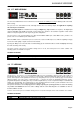
AVAILABLE VERSIONS 2 AVAILABLE VERSIONS 2.1 FM VERSION Thanks to its state-of-the-art digital technology, the processor integrates, as an option, a Stereo MPX coder (including composite clipper) and a RDS coder. The digital MPX stereo coder (optional) represents the ideal ‘final touch’ of processing. As it is directly built-in, it is totally harmonized with all other signal processing stages and ensures the best results in signal density while adhering to modulation limits.
AVAILABLE VERSIONS 2.2 ST / WEB VERSION The ST version with firmware version newer than 3.10 now includes also WEB processing for diffusing audio on the Web (Web-casting). The processor has active-balanced Left and Right channel, line level analog outputs for applications requiring discrete L/R processed audio. Audio input and outputs are available both in analog and digital way (digital available as an option). The digital input supports AES3/EBU and S/PDIF formats with several sample rates.
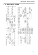
FM VERSION - BLOCK DIAGRAM 3 FM VERSION - BLOCK DIAGRAM – Page 7
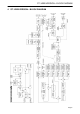
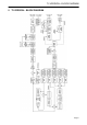
ST / WEB VERSION – BLOCK DIAGRAM 4 ST / WEB VERSION – BLOCK DIAGRAM Page 8
TV VERSION – BLOCK DIAGRAM 5 TV VERSION – BLOCK DIAGRAM Page 9
SAFETY WARNINGS / ISTRUZIONI PER LA SICUREZZA 6 SAFETY WARNINGS / ISTRUZIONI PER LA SICUREZZA SAFETY WARNINGS CONSIGNES DE SÉCURITÉ IMPORTANTES ISTRUZIONI IMPORTANTI PER LA SICUREZZA WICHTIGE SICHERHEITSHINWEISE INSTRUCCIONES IMPORTANTES DE SEGURIDAD (Rel. 1.2) 6.1 FOREWORD For your own safety and to avoid invalidation of the warranty all text marked with these Warning Symbols should be read carefully.
SAFETY WARNINGS 7 SAFETY WARNINGS The installation and servicing instructions in this manual are for use by qualified personnel only. - Read All Instructions. All safety and operating instructions must be read before operating the product. They also must be retained for future reference, as it contains a number of useful hints for determining the best combination of equipment settings for Yr particular application. - Heed All Warnings.
CONSIGNES DE SÉCURITÉ IMPORTANTES 8 CONSIGNES DE SÉCURITÉ IMPORTANTES - Lire ces consignes - Conserver ces consignes - Observer tous les avertissements - Suivre toutes les consignes - Ne pas utiliser cet appareil à proximité de l’eau - Ne pas obstruer les ouvertures de ventilation.
ISTRUZIONI IMPORTANTI PER LA SICUREZZA 9 ISTRUZIONI IMPORTANTI PER LA SICUREZZA - Leggere le presenti istruzioni - Conservare queste istruzioni - Osservare tutte le avvertenze - Seguire scrupolosamente tutte le istruzioni - Non usare questo apparecchio in prossimità di acqua - Non ostruire alcuna apertura per il raffreddamento.
WICHTIGE SICHERHEITSHINWEISE 10 WICHTIGE SICHERHEITSHINWEISE - Diese Hinweise LESEN - Diese Hinweise AUFHEBEN - Alle Warnhinweise BEACHTEN - Alle Anweisungen BEFOLGEN - Dieses Gerät NICHT in der Nähe von Wasser verwenden - KEINE Lüftungsöffnungen verdecken.
INSTRUCCIONES IMPORTANTES DE SEGURIDAD 11 INSTRUCCIONES IMPORTANTES DE SEGURIDAD - LEA estas instrucciones - CONSERVE estas instrucciones - PRESTE ATENCION a todas las advertencias. - SIGA todas las instrucciones - NO utilice este aparato cerca del agua - NO obstruya ninguna de las aberturas de ventilación.
UNPACKING AND INSPECTION ENG 12 UNPACKING AND INSPECTION Your equipment was packed carefully at the factory in a container designed to protect the unit during shipment. Nevertheless, we recommend making a careful inspection of the shipping carton and the contents for any signs of physical damage. Damage & Claims If damage is evident, do not discard the container or packing material. Contact your carrier immediately to file a claim for damages.
FIRST INSTALLATION RECOMMENDATIONS ENG 13 FIRST INSTALLATION RECOMMENDATIONS 13.1 POWER SUPPLY CABLE A power supply cable of approx. 2 mt length is supplied with the device, which has a moulded IEC plug attached – this is a legal requirement. The type of plug for the power supply depends on the country in which it is delivered.
FIRST INSTALLATION RECOMMENDATIONS ENG 13.3 FUSE REPLACEMENT The power supply socket has an integral fuse drawer containing the AC power fuse and a spare, both of the same value. BEFORE REPLACING THE POWER FUSE, MAKE SURE YOU HAVE THE RIGHT TYPE OF FUSE FOR THE VOLTAGE TO BE PROTECTED. USING WRONG FUSE TYPE WILL RESULT IN INSUFFICIENT PROTECTION. Make sure that the power is switched off and the power cable is disconnected from the equipment. Open the fuse drawer using a small blade screwdriver.
I/O BASIC SETTINGS ENG 14 I/O BASIC SETTINGS 14.1 ANALOG AUDIO INPUT IMPEDANCE The analog input impedance may be set to 600 Ohm, rather than the default 10 kOhm, by moving the two jumpers J1 and J2 on the analog input/output board (see figure below). INPUT INPEDENCE 604 OHM J1-J2 INPUT INPEDENCE 10K OHM 14.2 DIGITAL INPUT IMPEDANCE The digital input impedance may be set to 75Ohm, rather than the default 110Ohm, by moving the associated jumper on the digital I/O board (see figure).
I/O BASIC SETTINGS ENG 14.3 50 US / 75 US OUTPUT PREEMPHASIS SETTING (FM VERSION ONLY) The frequency characteristic of analog L & R outputs (XLR male connectors) can assume either a flat frequency response, or can follow a selected pre-emphasis curve, with or without subsequent de-emphasis. When ‘flat’ mode is engaged, this yields a signal with a flat frequency characteristic, but with an output ceiling that exactly follows the inverse of the pre-emphasis curve.
ENG MPX BOARD CONNECTIONS (FM VERSION ONLY) 15 MPX BOARD CONNECTIONS (FM VERSION ONLY) Available as an option on the FM version, the MPX board supports many configurations and operation modes. 15.1 DEFAULT MPX BOARD CONFIGURATION (FM-MPX VERSION ONLY) When not otherwise specified, the MPX board comes with J2, J4 and J5 jumpers closed and with OUT-2 output disabled.
MPX BOARD CONNECTIONS (FM VERSION ONLY) ENG The MPX OUT 1 (BNC connector) provides the FM composite signal + any RDS signal (internally generated or injected from an external encoder) and SCA signal. The MPX OUT 1 TEST connector provides a repetition of the output signal appearing at the main MPX OUT 1 connector, with the same level. The TEST output is individually buffered so that a short circuit on one output will not affect the other.
MPX BOARD CONNECTIONS (FM VERSION ONLY) ENG 15.
ENG THE ‘SPLIT’ MODE (FM VERSION ONLY) 16 THE ‘SPLIT’ MODE (FM VERSION ONLY) The MPX SPLIT mode (available as an option on FM version fitted with MPX option) allows the MPX OUT 2 output to toggle between an external MPX signal applied to AUX 1 input (or AUX 2 – see J1 and J3 jumpers) and the MPX signal internally generated. Switching is triggered by SPLIT Input on Digital Data Port (see paragraph 16.1).
THE ‘SPLIT’ MODE (FM VERSION ONLY) ENG EXAMPLE N° 1 – SPLIT activation by TTL command (connector internal view) external TTL signal must be applied through a 470 Ohm carbon resistor to the SPLIT photodiode (pins 1 and 2). Max current allowed: 10 mA.
GENERAL DESCRIPTION ENG 17 GENERAL DESCRIPTION 17.1 FRONT PANEL CONTROLS AND SIGNALLINGS The processor front panel contains 3 red LEDs with the following meaning: DIGITAL INPUT This LED lights up while the DIGITAL Audio input is selected (via front panel menu or Pc Software Control). , PREEMPHASIS This LED lights up while the Preemphasis (either 50 or 75 uSec) is removed from the processed Left and Right output XLR connectors. (NB preemphasis can NOT be removed from the MPX outputs).
GENERAL DESCRIPTION ENG 1 ON/OFF Switch: main ON/OFF switch, the LED inside switches on/off accordingly. The power supply socket (use the cord provided) has a built-in fuse drawer containing the power fuse and a spare, both of the same value: for 230 V AC the fuse is rated at 500 mA T; for 110 V AC it is rated at 630 mA T 2 RS232 Serial Port 2: This port is intended for the processor setting and programming from satellite and unidirectional links. Supported Baud Rate: 4800.
GENERAL DESCRIPTION ENG 17.3 DISPLAY DESCRIPTION 1. ON AIR Preset: shows the current processing curve. The presets ranging from 1 to 30 are factory preset, while curves 31 to 40 are user settable. A table showing the curve parameter levels is available on this manual. 2. AGC level: shows the gain factor that the processor applies to the input signal. The best AGC values range close to 0 dB (or, still better, are slightly negative: - 1, - 2, etc). 3.
AUDIO I/O AND SERIAL PORT WIRING ENG 18 AUDIO I/O AND SERIAL PORT WIRING Where possible use balanced connections for the audio inputs and outputs to minimise noise pick-up. Avoid running audio cables near to mains or lighting cables or thyristor dimmer units, power supplies etc. These may cause audible hum and buzz. The use of low impedance sources significantly reduces interference pick-up. Check the cables for correct wiring to avoid problems with phase reversal and unreliable connection.
ENG AUDIO I/O AND SERIAL PORT WIRING 8.2.1 Converting between AES/EBU and S/PDIF interfaces There are a number of differences in the electrical characteristics of AES/EBU and S/PDIF interfaces which in some cases can render them completely incompatible. Although the audio data is the same in both AES/EBU and S/ PDIF interfaces, they are indeed different formats, at least in their subcode. AES converted to coax is NOT S/PDIF, and S/PDIF converted to XLR balanced is NOT AES.
AUDIO I/O AND SERIAL PORT WIRING ENG 18.5 SERIAL PORTS The processor features two optoisolated serial ports for remote control through PC (connected directly or via satellite chain) of all machine functions and parameters. A standard, not crossed serial cable (9p male – 9p female) is provided with the equipment, compatible with all configurations.
ENG BROWSING THE MENU TREE 19 BROWSING THE MENU TREE This chapter describes all of the parameters and functions you can access and edit through the front panel of the audio processor, grouped according to functional area. See the Menu Tree on the following page. It is useful to note that you can also access all menu settings and parameters more quickly and conveniently through the PC control software. PRESETS (PROCESSING CURVES) The main menu displays the 30 factory preset and 10 editable curves.
BROWSING THE MENU TREE ENG To browse the menu: - The Enter button (or pressing the shuttle knob) has a dual function: to allow access to a menu sublevel, and to save a new parameter or function value. - The Esc button (or selecting ‘Quit’ and then pressing Enter) allows you to exit a menu sublevel or parameter editing screen (exit without saving) - Every time you access a parameter or function, the display shows its current value or status.
BROWSING THE MENU TREE ENG 19.
BROWSING THE MENU TREE ENG 19.
ENG BROWSING THE MENU TREE 19.
I/O CALIBRATION AND SYSTEM SETUP ENG 20 I/O CALIBRATION AND SYSTEM SETUP The processor is designed for easy installation and set up. All necessary interface connections are made through rear panel connectors. Refer to Rear Panel Connectors Chapter for a description and placement of each of the connections. With proper installation and calibration the processor will give you the most accurate results for audio processing and modulation.
I/O CALIBRATION AND SYSTEM SETUP ENG 20.2 ANALOG INPUT LEVEL ADJUSTMENT Skip this step if you are not using the analog inputs. This step calibrates the analog inputs to the level at which your studio system peaks its program material on the studio meters. This assures that the processing presets will operate in their optimal range. To take full advantage of the processor potential, the AGC value should normally operate in compression mode (meaning that it slightly reduces the input level).
I/O CALIBRATION AND SYSTEM SETUP ENG 20.4 VOICE CONTROL (ST AND FM VERSIONS ONLY) Some human voices (particularly male voices) exhibit as much as 6dB asymmetry in their waveform, while typical ‘musical’ signals are symmetric. As asymmetric clipped signals result in a more unpleasant ‘sound’ to the ear than the symmetric clipped ones, a filter designed to convert asymmetric waveforms into symmetric ones would be very recommended.
AGC CALIBRATION AND SETUP (FM and ST / WEB versions) 21 ENG AGC CALIBRATION AND SETUP (FM and ST / WEB versions) 21.1 AGC SPEED One of the most important processor function is the Automatic Gain Control (AGC) system, which compensates for variations in the input level to keep the signal at 0 dB.
AGC CALIBRATION AND SETUP (FM and ST / WEB versions) ENG For best performance, we recommend using Hold = 0Sec (Mode 2) for musical sources and Hold = 3 Sec (Mode 5) for ‘speech’ sources. The MaxG (Maximum Gain) parameter sets the maximum amplification value attainable by the AGC system. For instance, setting Mode 2 means that maximum amplification is +12dB: thus a –12dB signal can be compensated to 0, while a –15dB signal will reach a maximum of –3dB.
AGC CALIBRATION AND SETUP (TV version) ENG 22 AGC CALIBRATION AND SETUP (TV version) 22.1 OPERATIVE PRINCIPLES On the contrary of Radio broadcasting, the Tv audio broadcasting needs at the same time a good uniformity of the sound levels between different programs or contributions and the respect of original audio level of the program being processed (e.g. dialogs, sound effects of environment scenes, ‘silence’ passages of classical music and movies, etc).
AGC CALIBRATION AND SETUP (TV version) ENG 22.4 FLOOR AGC Floor AGC acts both on the digital and analogue inputs and set the compensation speed of the input signal level variation when its level ranges between Gate and Floor thresholds. In this range the original sound levels are mostly preserved and the processor interventions (as indicated by the low Agc values) are reduced to a minimum.
SETUP OF DISCRETE (L & R) AUDIO OUTPUT ENG 23 SETUP OF DISCRETE (L & R) AUDIO OUTPUT 23.1 ANALOG OUTPUT LEVEL You can adjust the analog audio output level (XLR connectors) through the Output Level control: DEFAULT SCREEN OUTPUT CALIBRATION menu OUTPUT LEVEL page The Output Level parameter expresses the peak value (in dBu) achieved by the audio output signal (which therefore corresponds to the maximum frequency deviation).
ENG SETUP OF DISCRETE (L & R) AUDIO OUTPUT 23.4 ANALOG OUTPUT PRE-EMPHASIS The XLRs analog output is intended for applications requiring discrete L/R processed audio. The frequency characteristic can follow a selected pre-emphasis curve, with or without subsequent de-emphasis. The factory-default setting is with pre-emphasis engaged, accordingly to the destination country (50 or 75 uSec).
SETUP OF DISCRETE (L & R) AUDIO OUTPUT ENG 23.6 DIGITAL AUDIO OUTPUT PRE-EMPHASIS (ST VERSION ONLY) The digital audio output (available as an option on the ST model) follows the same settings of discrete analog audio (ref to previous Section). Jumpers CN 17 and CN 18 must not be set! 23.
SETUP OF DISCRETE (L & R) AUDIO OUTPUT ENG To enable the output power limiting: DEFAULT SCREEN OUTPUT CALIBRATION menu POWER LIM(ITER) page OUTPUT POWER LIMITER The output power calculation does not take into account the injection values of the Pilot, external RDS signal and possible SCA signals. The following values are therefore assumed by default in the power calculation: Pilot = - 20dB, Rds = - 31.
SETUP OF WEB OUTPUT on the ‘ST’ version ENG 24 SETUP OF WEB OUTPUT on the ‘ST’ version The Web-designed output is recalled by the menu OutputCalibration->Preemphasis->WebRadio On the front panel. Alternatively, by using the Pc Control Software, You will find the Web Radio control on the Output Panel mask. The Pre-amphasis will be disangaged and therefore the standard Presets will become a bit more ‘open’ on high frequencies.
SETUP OF MPX OUTPUT (FM version only) ENG 25 SETUP OF MPX OUTPUT (FM version only) 25.1 MPX OUTPUT LEVEL* The MPX signal (+ any internally or externally generated RDS signal or SCA signal) is available on the Bnc MPX OUT connector. * the MPX module is available as an option The MPX output may be tuned using the small trimmer located next to the output BNC.
ENG SETUP OF MPX OUTPUT (FM version only) 25.2 MPX OUTPUT PREEMPHASIS (FM VERSION ONLY)* The Mpx output is with pre-emphasis always engaged, accordingly to the destination country (50 or 75 uSec).
SETUP OF MPX OUTPUT (FM version only) ENG 25.4 RDS SIGNAL LEVEL CONTROL (FM VERSION ONLY) *** The processor generated RDS signal level and phase can be adjusted by means of the RDS Module menu. DEFAULT SCREEN OPTIONAL CONTROLS menu RDS MODULE menu RDS LEVEL (or RDS PHASE) The RDS signal Level may be adjusted within the deviation range of 1.0 to 6.0 kHz (default operating level: -31.5dB, D=2.0 KHz). The relation between deviation and level is as in the following table: -37.5 dB -31.5 dB -28 dB -25.
ENG ADDITIONAL SETUP TASKS 26 ADDITIONAL SETUP TASKS 26.1 SERIAL PORT ENABLING (SERIAL MODULE) The Serial Module menu visualizes the status of the two serial ports RS 232 allowing their enabling or disabling. Remarks: - Ports are enabled by default (factory preset). - Firmware upgrade and remote control are possible only with enabled ports.
ENG ADDITIONAL SETUP TASKS 26.3 READING OUT THE FIRMWARE CODE The Firmware Code menu page displays the internal firmware serial code. The user must supply this number to the manufacturer in order to upgrade the processor firmware or add the RDS option. 26.4 READING OUT THE INTERNAL TEMPERATURE The Temperature sub-menu shows the internal temperature of the processor during operation. - The current temperature is updated each time this option is accessed.
CHOOSING THE PROCESSING CURVE (all versions) ENG 27 CHOOSING THE PROCESSING CURVE (all versions) 27.1 INTRODUCTION Once you have adjusted the input levels and reached the correct AGC level, you may move on to select the processing curve. The processor has 40 curves: the factory presets (PR) are stored in positions 01 through 30, while positions 31 to 40 may be set by the operator. As shown in the table on the next page, there are 10 parameters involved in processing.
CHOOSING THE PROCESSING CURVE (all versions) SUPER BASS PRESET DESCRIPTION LEVEL TYPE 01 CDG 02 CHI 03 DFW 04 FCO 05 MOW 06 SYD 07 TYO 08 ATH 09 HKG 10 MSY 11 VIE 12 ATL 13 JFK 14 MXP 15 YMQ 16 BER 17 LAX 18 RIO 19 SCL 20 BOM 21 LHR 22 MAD 23 BOS 24 SHA 25 YYZ 26 BUE 27 MEL 28 AMS 29 CCS 30 MEX FLAT FLAT FLAT FLAT LIVE LIVE VOCAL LIVE VOCAL POP POP POP LIVE POP LIVE SOFT SOFT DISCO VOCAL DISCO LIVE LOUD LOUD BASS BASS LOUD LOUD VOCAL VOCAL VOCAL VOCAL VOCAL 0 0 0 0 0 0 0 0 0 4 6 5 6 4 2 4 4 3 4 6 8 6 5
CHOOSING THE PROCESSING CURVE (all versions) ENG • Super Bass Level The Super Bass Level parameter sets the level of the Bass Enhancer effect added to the sound. The Bass Enhancer takes the bass signal from the 30Hz-200Hz range, and generates subharmonics that are filtered and modeled by the Super Bass Type, then once again injected onto the bi-channel signal, at the level set via the Super Bass Level control. Super Bass Level may be adjusted from 0.0 to +12.0 dB, with steps of 0.5 dB.
CHOOSING THE PROCESSING CURVE (all versions) ENG There are two ways to design or customize a curve: A. From among the existing curves, identify the one closest to the desired curve, make the changes deemed appropriate (for example, raise the level of mid tones or cut out low frequencies) and save the new curve thus obtained in one of the 10 locations set aside for the user (31 through 40). B.
THE PC CONTROL SOFTWARE (FM , ST/WEB, TV versions) - ENG when this option is selected with ‘Enter’, the changes made up until that moment will not be saved, and will be lost. by turning the shuttle clockwise instead you may find the position (thus the new curve) in which to save the changes. Once you have found the position (between 31 and 40), press ‘Enter’ twice. The processor will automatically put the new curve on the air. 28 THE PC CONTROL SOFTWARE (FM , ST/WEB, TV versions) 28.
THE PC CONTROL SOFTWARE (FM , ST/WEB, TV versions) ENG 28.3 MONO-DIRECTIONAL MODE (REMOTE) The picture shows the mono directional connection mode, which does not involve any return channel. It is possible to send commands to the equipment from remote sites, but does not allow either remote monitoring of the machine, nor confirmation of control reception. The typical application is centralized control – via satellite – of equipment installed at different transmitting sites.
THE PC CONTROL SOFTWARE (FM , ST/WEB, TV versions) ENG 28.4 INSTALLATION A) Using standard Windows procedures, access the PC REMOTE SOFTWARE folder and run the SETUP.EXE file under the Microsoft Windows® ’95, ’98, ME, 2000, NT and XP operating system. B) The install program installs Pc remote Control application onto the computer's hard disk. The installation screen will also suggest a destination directory for the software.
ENG THE PC CONTROL SOFTWARE (FM , ST/WEB, TV versions) 28.5 SOFTWARE SETUP Run the program. If it is unable to immediately establish an bidirectional connection with the processor, (as indicated by the display message ‘Remote data not Available’), a screen such as the following will appear: Click the ‘Setup’ key, and the following screen will appear: First of all, it is necessary to indicate which computer serial port is dedicated to the communication with the encoder (COM 1, 2, 3 or 4).
ENG THE PC CONTROL SOFTWARE (FM , ST/WEB, TV versions) It is now possible to set up or modify some modes regarding the software window display on the computer screen, and communications between the computer and the processor. - If selected, the option ‘Always On Top’ will always keep the control program window in the foreground of the desktop. - If selected, the option ‘High Rate’ allows you to select the higher refresh speed (30 Hz) in displaying the Vu Meter on the screen.
ENG THE PC CONTROL SOFTWARE (FM , ST/WEB, TV versions) 28.9 THE ‘RESTORE’ FUNCTION The ‘Restore’ function allows you to automatically reload the configuration present the last time the control program was closed. This is especially useful when you have inadvertently changed certain parameters or made configuration mistakes.
THE PC CONTROL SOFTWARE (FM , ST/WEB, TV versions) ENG 28.10 BI-DIRECTIONAL CONNECTION MODE As explained earlier, this mode (available only on port 1 of the processor) allows both the real time display and editing of all audio levels and current settings for all parameters used by the processor. Typical application: setting the processor directly at the transmitting site, using a notebook computer, or remote control from the broadcasting or control room, via serial cable.
THE PC CONTROL SOFTWARE (FM , ST/WEB, TV versions) ENG 28.11 THE ‘TARGET NAME AND GROUP NAME’ IDENTIFIERS As explained in the introduction, in bidirectional connection mode (local) it is possible to assign each processor with a specific identification code (called the ‘Target Name’), as well as a classification group, which is useful when you wish to selectively program the processor from remote sites over a unidirectional connection (see next chapter).
THE PC CONTROL SOFTWARE (FM , ST/WEB, TV versions) ENG 28.13 UNIDIRECTIONAL CONNECTION MODE The unidirectional connection mode is used to control one or more processors from a remote site, for example over a satellite link. In this case, it will only be possible to send commands or new values for operating parameters one way, without the ability to check whether the change has taken place or the current status.
THE PC CONTROL SOFTWARE (FM , ST/WEB, TV versions) ENG The submenus available are the same ones available with the bidirectional connection, thus: - The three buttons located alongside the display allow you to edit the new broadcast processing curve: select the curve from among the 40 available, using the two arrows, then confirm the choice using the rectangular button in the middle. The Edit submenu contains all of the parameters and operations regarding setting a new processing curve.
ENG Using the RDS SECTION (FM version ONLY) 29 USING THE RDS SECTION (FM version ONLY) The processor includes, as an option, a complete RDS encoder, programmable by a PC connected to its Serial Port 1 (bidirectional) or Serial 2 (monodirectional). This allows you to install encoders throughout the network, including local stations, and set them using a ‘master’ PC. The RDS upgrade procedure, if the RDS plug-in is not already present in your processor, is explained in one of the next chapters.
Using the RDS SECTION (FM version ONLY) ENG 29.2 RDS SERVICES - QUICK SUMMARY PI The PI code consists of four hexadecimal digits (see ‘Code’ field). The first identifies the country where the program is transmitted, the second digit identifies the type of broadcaster based on coverage area. Finally, the ‘Ref’ window must contain a number between 1 and 255 (normally assigned by the authorities).
Using the RDS SECTION (FM version ONLY) ENG 29.3 TA REMOTE CONTROL TROUGH OPTO INTERFACE The TA flag may be activated through a dedicated input on the OPTO INTERFACE port (the interface is available as an option). The OPTO-INPUT Port is a 9-pin female Interface (on DB-9 connector) which provides 2 optoinsulated “trigger” inputs: one for SPLIT mode activation and one for TA flag switching Once enabled, TA input activation will cause WARNING LED on Front Panel to light.
Using the RDS SECTION (FM version ONLY) ENG 29.4 PS (PROGRAM SERVICE NAME) PANEL Click the PS button to access the main PS message panel (Program Service Name). All mobile and fixed receivers display this message. The PS panel allows to transmit single PS messages, PS sequences as well as PS Scrolling messages. 29.5 SINGLE PS OR PS SEQUENCES The Program Service Panel allows You to easily create and broadcast sequences composed by up to 32 PS Names, of 8 characters each..
ENG Using the RDS SECTION (FM version ONLY) EXAMPLE 2 Accordingly to the settings in the picture here eabove, the processor will transmit 1 fixed PS (R.FOUR), displayed at all time. 29.6 PS IN SCROLLING MODE Alternatively to PS Sequences or fixed PS message, the PS panel allows You to enter one PS message which will scroll on the receiver display. It means, text is moved right to left across the display one OR MORE characterS at a time at the rate set by the user (TIME).
Using the RDS SECTION (FM version ONLY) ENG 29.7 HINTS AND TIPS ABOUT DYNAMIC PS MODE When programming PS durations in Dynamic mode, two ‘gold’ rules should be taken into account. They are related to the ‘physics’ of RDS channels and are completely independent from RDS encoder architecture. WARNING: if the PS is constantly changed (as in the PS Scrolling mode), it is possible that some receivers will display a mixture of old and new PS message on the same display.
Using the RDS SECTION (FM version ONLY) ENG 29.9 AF METHODS A AND B There are two ways to transmit lists of alternative frequencies: Method A and Method B. In both cases the lists should include only those frequencies for the nearest transmitters and repeaters (with overlapping coverage areas). Generally speaking, Method A is used when the list contains no more than 25 frequencies, and Method B when the list is longer (for a maximum of 24 lists).
Using the RDS SECTION (FM version ONLY) ENG As mentioned earlier, Method B is used with high numbers of alternative frequencies and/or when the transmitter also has frequencies that broadcast different radio program at various times of day (splitting, local programming, etc.). In the latter instance, the mobile receiver should check whether the AF is broadcasting the same content before selecting another frequency.
ENG Using the RDS SECTION (FM version ONLY) 29.10 HOW TO GET THE RDS OPTION AFTER PURCHASING THE EQUIPMENT The RDS option could be pre-installed in the factory if notified when ordering the unit or it can be installed at the customer’ premise after receiving it. In the latter case, the RDS software must be activated with a proper Activation Key, uniquely determined by your unit firmware's serial number.
FIRMWARE UPGRADE PROCEDURE ENG 30 FIRMWARE UPGRADE PROCEDURE The processor comes from the factory with the most recent firmware installed just prior to shipping. When required, the firmware can be updated with the latest available version using standard Windows procedures.
FIRMWARE UPGRADE PROCEDURE ENG NOTE: depending on the processor version, the two motherboards could present 4 programming Jumpers (JP1, JP2, CN5, CN6) instead of 5 G) Turn the processor on. 2) RUNNING THE UPGRADE FILES ON THE PC G) Close all opened applications on the PC.
FIRMWARE UPGRADE PROCEDURE J) ENG Select the PC serial port on the screen K) Click Request button. L) Make sure the Identification is correctly done (Processor Identification passed message + firmware code displayed in the right field), and click ‘UpGrade’. The upgrade will continue automatically. NOTE: the upgrade processing must not be interrupted. NOTE: once the upgrading procedure has started, it must NOT be interrupted for any reason.
FIRMWARE UPGRADE PROCEDURE ENG D) Copy (or move) the RDS key (unzipped) into that Firmware_Upgrade folder E) Run the file DAP_Vxy_STD_RDS: the Upgrader will automatically check the presence of the enabling ‘key’ in the same folder F) Follow points I) throughout N) described at Paragraph 2) With RDS option NOT installed, the processor will display the message ‘RDS DEMO SIGNAL’ when accessing the Optional Controls/RDS Module/RDS Level menu.
TECHNICAL SPECIFICATIONS - FM version ENG 31 TECHNICAL SPECIFICATIONS - FM version GENERAL FEATURES Environmental 0 to 45 °C, 0-95% RH, non-condensing Dimensions 1 rack unit, 352 x 483 x 44 mm Net Weight around 7 Kg AC Rate Power consumpt. Shipping Weight 230 Vac / 110 Vac - 50 / 60 Hz 40 Watt around 8 Kg ANALOG STEREO AUDIO INPUT Conversion 48 KHz, 24 bit Connector Type XLR female electronically balanced Max Input Level + 22 dBu Nominal Inp Level 0 dBu +/- 6dBu Inp.
TECHNICAL SPECIFICATIONS - FM version Order-Butterworth) Bass Enhancer Programmable HF Limiter Filter IIR 2nd, 6KHz High Freq Threshold Adjustable –51 to -80 dB Denoiser MPX OUTPUT Configuration 2 BNC floating over chassis, EMI supp. + 1 output for measurement or test Level control Recessed trimmer D/A Conversion Burr Brown PCM56, 16-bit Pilot Frequency 19 KHz ± 2 Hz ** –17.25 to –23 dB (0.
TECHNICAL SPECIFICATIONS - ST / WEB version ENG 32 TECHNICAL SPECIFICATIONS - ST / WEB version GENERAL FEATURES Environmental 0 to 45 °C, 0-95% RH, non-condensing Dimensions 1 rack unit, 352 x 483 x 44 mm Net Weight around 7 Kg AC Rate Power consumpt. Shipping Weight ANALOG STEREO AUDIO INPUT Conversion 48 KHz, 24 bit Connector Type XLR female electronically balanced Max Input Level + 22 dBu Nominal Inp Level 0 dBu +/- 6dBu Inp. Level Range - 20 dB to 20 dB Impedance 600Ohm / 10KOhm EMI –suppressed Dyn.
TECHNICAL SPECIFICATIONS - ST / WEB version ENG SIGNAL PROCESS FILTERS USER CONTROLS Sampling rate Super Bass Type Disco Soft Bass, Club Long Bass, Tight Hard Bass Super Bass Level 0 to +12dB Bass Thr Level Adj.– 6 to + 6 dB (0.5 dB step) Mid1 Thr Level Adj.– 6 to + 6 dB (0.5 dB step) Mid2 Thr Level Adj.– 6 to + 6 dB (0.5 dB step) Mid3 Thr Level Adj.– 6 to + 6 dB (0.5 dB step) High Thr Level Wide Density Adj.– 6 to + 6 dB (0.
TECHNICAL SPECIFICATIONS – TV version ENG 33 TECHNICAL SPECIFICATIONS – TV version GENERAL FEATURES Environmental 0 to 45 °C, 0-95% RH, non-condensing Dimensions 1 rack unit, 352 x 483 x 44 mm Net Weight around 7 Kg ANALOG STEREO AUDIO INPUT Conversion 48 KHz, 24 bit Connector Type XLR female el. balanced Max Input Level + 22 dBu Nominal Inp Level 0 dBu +/- 6dBu Inp. Level Range - 20 dB to 20 dB Impedance 600Ohm / 10KOhm EMI –suppressed Dyn.
WARRANTY Mid2 Band Filter Mid 3 Band filter High Band filter Bass Enhancer HF Limiter Filter HiFreq Denoiser Band Pass 1.5Khz-4.8Khz (IIR 4th Order-Butterworth) Band Pass 4.8Khz-9.5Khz (IIR 4th Order-Butterworth) Band Pass 9.5Khz-15KHz (IIR 4th Order-Butterworth) Programmable IIR 2nd, 6KHz Threshold Adjustable –51 to -80 dB ENG Mid1 Thr Level Adj.– 6 to + 6 dB (0.5 dB step) Mid2 Thr Level Adj.– 6 to + 6 dB (0.5 dB step) Mid3 Thr Level Adj.– 6 to + 6 dB (0.