Click Here www.FordManuals.
Copyright © 2006, Forel Publishing Company, LLC, Woodbridge, Virginia All Rights Reserved. No part of this book may be used or reproduced in any manner whatsoever without written permission of Forel Publishing Company, LLC. For information write to Forel Publishing Company, LLC, 3999 Peregrine Ridge Ct., Woodbridge, VA 22192 1967 Cougar, Fairlane, Falcon, Mercury and Mustang Shop Manual ISBN: 0-9673211-4-X EAN: 978-0-9673211-4-1 Forel Publishing Company, LLC 3999 Peregrine Ridge Ct.
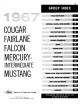
GROUP INDEX 1 2 3 4 5 6 7 VEHICLE IDEMIIRCATION BRAKES SUMMON, STEERING, INNERS AND TIRES REAR AXLE NW- DRIVE SHAFT AND CLUTCH MANUAL SHIFT TRANSMISSION . AUTOMATIC TRANSMISSION ENGINE FALCON MERCURY- 1GNRION SYSTEM :. FUEL SYSTEM COOLING SYSTEM EXHAUST SYSTEM imam SYSTEM MUSTANG Mir ' SMOG VARTIHG SYSTEM SYSTEM, HORNS AND INSTRUMENTS MPIMI.ATING, HEATING AND ACCESSORIES nt.
FOREWORD This shop manual provides the Service Technician with information for the proper servicing of the 1967 Cougar, Fairlane, Falcon, Mercury Intermediate, Comet and Mustang cars. The maintenance schedule and procedures for maintenance operations are published in the 1967 h s e n g e r Car Maintenance and Lubrication Manual.
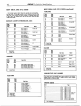
1-2 GROUP 1-Vehicle Identification BODY SERIAL AND STYLE CODES-4continu.d) BODY SERIAL AND STYLE CODES FAIRLANE The two-digit numeral which follows the assembly plant, code identifies the body series. This two-di it number i s used in coniunct~onwith the Body Style Code, in the Vehicle bate, which consists of a two-d~gitnumber with a letter suffix. The following chart lists the Body Serial Codes, Body Style Codes and the model.
GROUP I-Vehicle Identification T R A N S M I S S I O N CODES TYP Code 1 .............................................................................................S p e e d Manual 2 ............................................................................................ Overdrive 3 .............................................................................................S p e d Manual 5 .............................................................................................
GROUP 1-Vehicle Identification EXTERIOR PAINT COLOR CODES Code M30-J M32-J INTERIOR TRIM CODES-(continued) Color A ........................................... 1724-A ...................................... Bbc k B...........................................A ...................................... L t Aqua E ........................................... 2 0 4 5 ...................................... M e . Beige Met. I...........................................2 1 ......................................
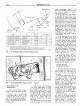
2-2 GROUP 2-Brakes STEERING WHEEL RIM N O T E : A DIMENSION T O i3E MEASURED T O SHEET M E T A L B DIMENSION T O B E MEASURED P A R A L L E L 70 THE V E R T I C A L C E N T E R L I N E OF T H E STEERING COLUMN WlTH A 50 POUND L O A D A P P L I E D TO T H E C E N T E R L I N E OF THE B R A K E P E D A L PAD. (CHECKS ON POWER B R A K E V E H I C L E S M A D E WlTH ENGINE RUNNIP4C-l FIG.
PART 2-1-General be required to hold the pedal in the applied position. I f no action is felt, the vacuum booster system is not functioning. LOCKED WHEEL BRAKE Should one of the wheel brakes be locked and the car must be moved, open the bleeder screw long enough to let out a few drops of brake fluid. This bleeding operation will release the brakes but will not correct the cause of trouble.
GROUP 2-Brakes \ CONVERTIBLE NU'L PARKING eERAKE R A K E CA: Y RETAINER-74277.5 AND CONDUIT , ASSEMBLY-2853 \ , SPRING-2A651 CAaLE ASSEMSLY A / 2A604 , 7-10 LB.FT. \LR~'~AINER-~A~I~ CONVERTIBLE ONLY FIG. 5-Parking Adjustment Falcon r - H1553-A Brake Linkage Comet, Fairlane a n d FIG. 7-Push Rod Adjustment - Midland-Ross T o check the adjustment of the screw, fabricate a gauge of the dimension shown in Fig. 6.
PART 2-1-General Brake Service APPROXIMATELY 45" H1300-A FIG. 9- Wrench for Bleeding Brake Hydraulic System and install the master cylinder cover and gasket. Be sure the diaphragm type gasket is properly positioned in the master cylinder cover. When the bleeding operation is completed, the fluid level should be filled to within 114 to 112 inch from the top of the reservoirs. 7.
GROUP 2-Bra kes CLEANING AND INSPECTION D I S C ( F R O N T ) BRAKES 1. Remove the wheel and tire, caliper splash shield, and the shoe and lining assemblies as outlined in Part 2-2, Section 2. 2. Make three thickness measurements with a micrometer across the middle section of the shoe and lining. Take one reading at each side and one in the center. If the assembly has worn to 'a thickness of 0.231 inch (shoe and lining together) or 0.
- PART 2-1-General Brake Service Trouble Symptoms t C C - =0 L O II),m 3 m c ..
2-8 GROUP 2-Bra kes Trouble Symptoms t0 C z - .P Y 4) 4 al 2 - r - r 'Possible Causes Of Trouble X Mechanical Resistance at Pedal or Shoes I Warning Lamp Switch Is Inoperative FIG.
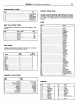
I Section Page 1 Description and Operation ..........................2-9 Dual-Master Cylinder Brake System ...........2-9 2-1 1 Disc Brakes ........................................... Hydraulic Self-Adjusting Brake System ........2-13 Booster System ..................................... .2-13 Parking Brakes ......................................2-14 2 In-Vehicle Adjustments and Repairs ..............2-14 Front (Disc) Brake Shoe and Lining Replacement .......................................
GROUP 2-Bra kes secondary (rear brake) master cylinder pistons are moved simultaneously to exert hydraulic fluid pressure on their respective independent hydraulic system. The fluid displacement of the duallmaster cylinders is proportioned to fulfill the requirements of, each of the two independent hydraulic brake systems (Fig. 2). If a failure of the rear (secondary) brake system should occur, initial brake pedal movement causes the unrestricted secondary piston to bottom in the master cylinder bore.
2-1 1 PART 2-2-Brake System the rear brake system outlet port (Fig. 4). Movement of the differential valve forces the switch plunger upward over the tapered shoulder of the valve to close the switch electrical contacts and light the dual brake warning lamp, signalling a brake system failure.
WTRAN CALIPER TO ROTOR CLEARANCE I FIG. 6-Typical TUBE Caliper Assembly-Sectional View PISTON 1 FIG. 5-Typical Disc Brake Assembly t o seal the cylinder bore from contamination (Fig. 6). Square-section rubber piston seals are positioned in grooves in the cylinder bores. The piston seals perform three important tasks: 1. They provide hydraulic sealing between the cylinders and pistons. 2. They return the pistons t o released position, when hydraulic pressure is released. 3.
2-1 3 PART 2-2-Brake System CLIP MUST NOT TOUCH OR COVER RUBBER RING AROUND OUTSIDE OF VALVE ASS,EMBLY TUBE-2265 DlSC BRAKE CONTROL TORQUE TO 6.15 LB. F T . A TUBE-2265 I PROPORTIONING VALVE ASSEMBLY-26272 TUBE-2B113 FLAT SlDE 0F"D" SHAPED HOLE MUST BE LOCATED ON INBOARD SlDE OF HOSE BRACKET DlSC BRAKE PRESSURE CONTROL VALVE ASSEMBLY-ZBOPI HOSE-2A448 INSTALLATION-DISC BRAKES ONLY NG. 8-Disc BOLT-376459.
GROUP 2-Bra kes 2-1 4 FIG. 10-Self Adiusting Brake Assemblies- manifold vacuum and atmospheric pressure for its power. Adjllstment of the push rod is the only service permitted on a brake booster. The booster unit is to be exchanged when i t is inspected, checked and found to be defective. PARKING BRAKES-MUSTANG A N D COUGAR An independent hand-operated parking brake control actuates the rear wheel brake shoes through a cable linkage.
PART 2-2-Bra ke System Tool - HRE8650 FIG. 1 ]-Measuring Drum ing the tool and the procedure detailed below. When adjusting the rear brake shoes, check the parking brake cables for proper adjustment. Refer to Parking Brake Linkage Adjustment, Part 2-1, Section 2. Make sure that the equalizer operates freely. To adjust the brake shoes: 1. Using Rotunda Tool H R E 8650, (Fig. I I) determine the inside diameter of the drum braking surface. 2. Reverse the tool as shown in Fig.
GROUP 2-Bra kes BRAKE SHOES A N D ADJUSTING SCREW REMOVAL 1. With the wheel and drum removed, install a clamp over the ends of the wheel cylinder as shown in Fig. 14. 2. Remove the brake retracting springs +sing Tool 2035-N or 2086L (Fig. 14). 3. Disconnect the brake shoe holddown springs and remove the brake shoe assemblies along with the complete automatic adjustment mechanism. 4. Disassemble the brake shoes. 5. On rear brakes, remove the parking brake link and spring from the brake assemblies.
PART 2-2-Bra ke System- ADJUSTING SCREW IDENTIFICATION LINES FIG. 16-Adjusting H1143-0 Screw and Lever Identification e. See that the adjusting screw socket is properly seated in the notch in the shoe web. DISC BRAKE SHOE AND LINING REPLACEMENT DISC BRAKE SERVICE PRECAUTIONS 1. After any brake service work, pump the brake pedal to obtain a firm pedal before moving the car. Riding the brake pedal (common on left foot applications) should be avoided when driving the car. 2.
GROUP 2-Brakes Be sure that the tabs on the shoe flanges seat fully against the caliper bridges (Fig. 18). 2. Position the spring clips on the calipers and install the retaining bolts and washers (Fig. 17). 3. Pump the brake pedal several times until a firm pedal is obtained and the shoe and lining assemblies are properly seated. 4. Install the wheel and tire on the hub and rotor assembly. 5. Check and refill the master cylinder reservoir with specified brake fluid as required.
PART 2-2-Brake System DlSC BRAKE ROTOR SPLASH SHIELD REMOVAL 1. Remove the caliper and the hub and rotor assembly as outlined under Removal in the foregoing procedure. 2. Remove the four nuts that attach the splash shield to the mounting bracket and remove the shield (Fig. 17). 3. Remove the gasket. BOOT \ Q PISTON FRONT BLEEDER SCREW INSTALLATION 1. Install the gasket. 2. If the shield is bent, straighten it out before installation.
GROUP 2-Brakes 2. Place a clamp over the ends of the wheel cylinder as shown in Fig. 14). 3. Remove the brake shoe assemblies; following procedures outlined in this section. 4. Disconnect the brake line from the brake cylinder. To disconnect the hose at a front cylinder, remove the tube fitting that connects the opposite end of the hose to the brake tube at a bracket on the side rail.
2-2 1 PART 2-2-Bra ke System CLIP MUST NOT TOUCH OR COVER RUBBER RING AROUND OUTSIDE *HOSE -2078 2 RE.QUlRED 'UBE -2265 TUBE-2B112 C LIP-26266 TUBE BOLT-378459.SZ TORQUE TO 27-32 LB. FT. VlEW I N C I R C L E P TO RETAIN SHOWN VlEW I N C I R C L E T TORQUE TO 12-18 LB. FT. INSTALLATION-DISC BRAKE ONLY I N S T A L L A T I O N - D I S C B R A K E S SAME AS DRUM B R A K E S AND M A l N VlEW E X C E P T AS SHOWN , TUBE-2267 R.H. TUaE-2265 CLIP-381 788.
2-2 2 GROUP 2-Brakes TIGHTEN A L L 3/8-24 7/16-24 1/2-20 9/16-18 GASKET-2149 2 REQUIRED HYDRAULIC LINE CONNECTIONS AS FOLLOWS: THREAD 8-15 FOOT POUNDS THREAD -10-18 FOOT POUNDS THREAD 12-20 FOOT POUNDS THREAD 15-25 FOOT POUNDS TORQUE T O 12-18 FOOT POUNDS BODY CROSSMEMBER WASHER-34808.
PART 2-2-Brake System R E M O V A L A N D INSTALLATION DUAL MASTER CYLINDER STANDARD BRAKES RETAINER I REMOVAL Refer to Figs. 22 and 23. 1. Working from inside the vehicle below the instrument panel, disconnect the master cylinder push rod from the brake pedal assembly. The push rod cannot be removed from the master cylinder. 2. Disconnect the stoplight switch wires at the connector. Remove the hairpin retainer.
GROUP 2-Bra kes 2-24 Snap Ring P l i e r s / H1477-B FIG. 24-Removing Typical Snap Ring- 19542-A (ESA-M6C25-A) for disc brake applications, and Rotunda Brake Fluid - Part Number B7AZ19542-A, R 103-A or equivalent for power drum and standard brake applications. The brake fluid is colored blue for identification. D o not mix low temperature brake fluids with the specified fluid for the power disc brake system. 8. Bleed the dual-master cylinder and the vrimary and secondaw brake systems.
PART 2-2-Bra ke System 6. Disconnect the secondary system rear brake outlet tube from the lower side pressure differential valve assembly. 7. Remove the screw retaining the pressure differential valve assembly to the vehicle and remove the differential valve assembly. 8. If the differential valve is to be replaced, remove the brake warning lamp switch and install the switch in the new differential valve.
GROUP 2-Brakes gine oil to the bushings and locate all bushings in their proper places on the clutch and brake pedal assemblies. 2. Position the brake pedal to the support bracket, then install the clutch pedal and shaft assembly through the support -bracket and brake pedal assembly. lnstall the spring washer and retainer. (Fig. 22 and 23). 3. lnstall the split bushing in the spring groove of the clutch pedal. Hook the clutch assist spring to the groove and to thespring retainer. 4.
PART 2-2-Bra ke System SHAFT (AUTOMATIC) TRANSMISSION-2478 CLUTCH PEDAL ASSEMBLY BRAKE PEDAL FIG. 26-Removing Pistons or Installing bly from the bracket on the inner side rail. 5. Disconnect the cable stepped-rod from the equalizer lever. Pull the cable forward through the crossmember and remove the cable from the vehicle. INSTALLATION 1. Pass the stepped-rod rearward through the crossmember and connect it into the equalizer lever. 2.
2. With the cables slack, disconnect the ball-ends from the connector (Fig. 27). 3. Remove the cable from the retainer hooks (station wagon models) and the underbody guide (convertible models) if required. 4. Remove the hairpin lock retaining the cable housing to therside rail bracket. 5. Remove the wheel cover, wheel" and tire and the rear brake drum as outlined in Section 2. 6. Remove self-adjuster springs to allow clearance to remove cable retainer from the backing plate.
PART 2-2-Brake System must not exceed 0.002 inch total indicator reading, and the surface finish of the braking surfaces are to be 85/15 micro inches. The minimum limiting dimensions (Fig. 10, Part 2-1) from the inboard bearing cup to the outboard rotor face (dimension A) and from the inboard rotor face (dimension B) must be observed when removing material from the rotor braking surfaces. HAlR PIN RETAINER-380699-S2 / sPAcg-,rlsal.
GROUP 2-Brakes VACUUM TUBE-2420 SHAFT STANDARD TRANSMISSION FIG. 30-Vacuum AUTOMATIC TRANSMISSION Brake Booster Installation - Mustang and Cougar using a master cylinder repair kit, install all the parts supplied. 2. Check all recesses, openings and internal passages to be sure they are open and free of foreign matter. Use an air hose to blow out dirt and cleaning solvent. Place all parts on a clean pan or paper. 3. Inspect the master cylinder bore for signs of etching, pitting, scoring or rust.
PART 2-2-Brake System FIG.
GROUP 2-Brakes 2-32 SAME AS MAIN VIEW EXCEPT AS SHOWN FOR FAIRLANE-COMET STATION WAGONS AND A L L FALCON MODELS CABLE-2A60d CABLE -2A604 7-10 LB. FT. RETAINER-2A709 STATION WAGON ONLY A L L EXCEPT 390 ENGINE BOLT-3740324 PARKING BRAKE LEVER PEDAL PAD COVER-2A798 7-10 LB. FT. AND CONDUIT-2853 CONVERTIBLE ONLY .USE ON COMET-CALIENTE, CYCLONE, CYCLONE "GT" AND FAIRLANE 5 0 0 X L MODELS ONLY FIG.
PART 2-2-Brake System 2. The new caliper seals must be flat-round and not twisted when setting freely on a clean surface. Discard any new seals that have been deformed in shipping or storage. Installation of deformed seals may result in seal leakage. 3. Apply a film of clean brake fluid to new caliper piston seals and install them in the grooves of the cylinder bore. The seal should be positioned at one area in the groove and gently worked around. D o not re-me the original seals. 4.
PART 2-3.-Specifications CHECKS A N D ADJUSTMENT4NCHES -..- - . H1514-A Cougar, Mustang - Comet, Falcon, Fairlane (3 Description B r a k e Pedal Height and Travel Measurements Power . - . Brake Push Rod Adiustment Bendix 0.9804.995 Midland Ross 0.9804.995 Lining Maximum Wear L i m i t (From Top of Rivets or Shoe Rim) Lining Maximum Clearance t o Shoe - $2 0 1/32 1I32 D r u m Diameter Self Adiustment Cable Lennt hEnd ~ a i i eAnchor t o End o r c a b l e Hook .i, Refer t o Part 2-1. Section 1.
PART 2-3 5 2-3-Specifications L I N I N G D I M E N S I O N S - D R U M BRAKES-INCHES ( C O N T I N U E D ) I Mustang and Cougar I Comet and Fairlane Passenger Car (200 & 289 ClD Engine)-Except Convertible Passenger Car (390 CI D Engine), S t a t i o n Wagon and Convertible (200 & 289 Engines), LPO P o l i c e 4 a x Fade Resistance Fairlane-Comet LPO Taxi-Maximum Wear Resistance (Bonded) Stat i o n Wagon (390 CID Engine) I Position Primary Secondary Primary Secondary Primary Secondary Primary Second
2-36 GROUP 2-Brakes TORQUE LIMITS (FTdBS)&ENERAL I -- HISIS-A Description Parking Brake Control Assembly Mounting Bolt Master Cylinder t o Dash Panel Bolts Brake Pedal support Bracket t o Instrument Panel Wheel t o Hub and Drum Nuts 4- Lug 5- Lun Hydraulic Line Connections -Nut Sizes 3 3/8-24 7/16-24 Comet Fairlane 15-20 15-20 Falcon 15-20 18-25 Cougar Mustang 15-20 18-25 70-1 15 55-85 70-115 55-85 70-115 8-15 10-18 -Brake Hose Connections Wheel Cylinder Caliper I - - - 17-25 2732 Front Br
GROUP 3-Suspension, Steering, Wheels & Tires Pump, Control V a l v e , a n d P o w e r C y l i n d e r Leak If the fittings and connections do not leak, check the other parts of the system. Check the hose connection at the pump for leaks, and tighten the hose clamp if necessary. P u m p Leaks If leakage occurs at the pump reservoir seal, or pump outlet fitting seal, check the torque of the outlet valve nut.
PART 3-1-Suspension, Steering, Wheels And Tires General Service , - Tool - T65P3000:e / 1 - 3-3 or-! - 1 - MUSTANG FAIRLANE FALCON - COUGAR C M E T - F O R D . MERCURY FIG. 3-Typical Front Alignment Spacer Installation REAR SPACER FRONT SPACER F 1352-A FIG. 2-Alignment Spacers Modification ing the caster and camber, the suspension alignment spacers must be installed to obtain the curb heights. I 1 1 I i FRONT SPACER I. Mustang H.P.
3-4 GROUP 3-Suspension, Steering, Wheels & Tires wheels in ,the straight-ahead position. Run the engine so that the power steer-ing control valve will be in the center (neutral) position (if so equipped). Measure the distance be- tween the extreme front and also between the extreme rear of both front wheels. The difference between these two distances is the toe-in. Correct toe-in, or inward pointing of both front wheels at the front, is specified in Part 3-6.
PART 3-1-Suspension, Steering, Wheels And Tires G e n e r a l Service W H E N TOE-IN I S CORRECT: TURN BOTH CONNECTING ROD SLEEVES UPWARD TO ADJUST SPOKE POSITION FIG. 8-Spindle Connecting Rod Sleeve- Typical sition, lengthen or shorten both rods equally to obtain correct toe-in (Fig. 9). If the steering wheel spokes are not in their normal position, make the necessary rod adjustments to obtain correct toe-in and steering wheel spokealignment (Figs. I0 and I). 3.
3-6 . . GROUP 3-Suspension, Steering, Wheels. & Tires rise within the upper cover bolt hole; then slowly turn the steering wheel to the left stop, lubricant should rise within the filler plug hole. If lubricant does not rise in both the cover bolt hole and the filler plug hole, add lubricant until it comes out both holes during this check. 6. Install the upper cover-to-housing attaching bolt. COMET,'FALCON, AND FAIRLANE 1. Center the steering wheel. ' 2.
This is only a Demo of the product! Only a few pages are included. Description: The Ford Shop Manual is the original manual used by the Ford dealership mechanics at to guide them through repairs and maintenance. Each section provides information on the operation of major systems, Our manuals are fully diagnostics, troubleshooting, overhaul, as well as the approved and licensed by removal and installation of major components.
Visit us online for other great Ford Products: