
Specifications

2-2
GROUP
2-Brakes
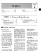
STEERING WHEEL RIM
NOTE: A DIMENSION TO
i3E MEASURED TO SHEET METAL
B DIMENSION TO BE MEASURED PARALLEL
70
THE VERTICAL CENTERLINE
OF
THE
STEERING COLUMN
WlTH A
50
POUND LOAD APPLIED TO THE CENTERLINE OF THE
BRAKE PEDAL PAD. (CHECKS ON POWER BRAKE VEHICLESMADE
WlTH ENGINE RUNNIP4C-l
H1551-~
FIG. I-Brake Pedal Height and Travel Measurements
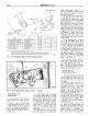
FIG. 2-Brake Pedal
Effort
Gauge Installed
-
Typical
Brake Pedal Travel
Measurement
1.
Install a Brake Pedal Pressure
Gauge on the brake pedal pad (Fig.
2).
2.
Hook a steel measuring tape
to the brake pedal as shown in Fig.
I. Measure and record the distance
from the brake pedal free height po-
sition to the reference point, which is
at the six o'clock position on the steer-
ing wheel rim.
3.
With the steel tape still hooked
to the brake pedal depress the brake
by pressing downward on the
brake
pedal effort gauge. Apply a 50
pound load to the center of the pedal
by observing the pressure gauge,
agd measure the distance ffom the
brake pedal to the fixed reference
point on the steering wheel rim,
parallel to the ccnterline of the steer-.
ing column.
4.
The difference between the brake
pedal free height and the depressed
pedal measurement under a 50
pound load should be within the speci-
fied maximum pedal travel service
specification B in Fig.
1.
5.
If
the pedal travel is more than
the specified maximum shown in Fig.
I,
dimemion B, make several sharp
reverse stops (equivalent to 50 pounds
pedal pressure) with a forward stop
before each. Move the, car in reverse
and forward for a distance of ap-
proximately ten feet; then apply the
brakes sharply
and hold the brake
pedal down until the car is completely
stopped. This will actuate the brake
self-adjusters.
If
these stops do not
bring the brake pedal travel with-
in specification, make several addi-
tional forward and reverse stops as
outlined above.
6.
If
the second series of stops do
not bring the brake pedal travel
within specification, remove the brake
drums and check the brake adjusters
to make sure they are functioning.
Check the brake linings for wear or
damage. Repair or replace all worn
or damaged parts and
non-function-
ing adjusters. Adjust the brake lin-
ing outside diameter to The approxi-
mate inside diameter of the brake
drlrm wi!h Rotunda Too! HRE 8650
(Figs.
I
I
and 12, Part 2-2).
7.
If all the brake adjusters.
brake drums and linings are func-
tional and the brake pedal travel is
not within specifications, check the
pedal linkage for missing bushings.
or loose attachments. Bleed the brake
and centralize the differential valve.
POWER BRAKE
FUNCTIONAL TEST
I.
With the transmission in neutral.
stop the engine and apply the parking
brake. Depress the brake pedal sev-
eral times to exhaust all vacuum in
the system.
2.
With the engine shut off. de-
press the brake pedal and hold it in
the applied position.
If
the pedal
gradually falls away under this
pressure, the hydraulic
system is
leaking. Check all tubing, hoses.
calipers (if so equipped), wheel cyl-
inders and connections for leaks.
If
the brake pedal movement f&ls
spongy, bleed the hydfaulic system
to remove air
from the system. Refer
to Hydraulic Systern Bleeding, Part
1, Section 2. Also, check for leaks or
insufficient fluid.
3.
With the engine shut off and
all vacuum in the system exhausted,
depress the pedal arid hold it in the ap-
plied position. Start the engine.
If
the
vacuum system is operating, the
pedal will tend to fall .away under
foot pressure and less pressure will