Product User Manual $;,207(. and enterprise branch and head offices MANO870 www.enochsystems.com 1-877-722-1116 sales@enochsystems.com Copyright © 2013 Enoch Systems, LLC, Enoch Systems and the Enoch Systems logo are trademarks or registered trademarks of Enoch Systems, LLC and/or its affiliates in the U.S. and other countries. Third-party trademarks mentioned are the property of their respective owners. All rights reserved.
MANO870 Series ® Intel QM77 with Intel CoreTM i7 / i5 / ® ® i3 / Pentium / Celeron Mobile CPU Mini ITX Motherboard User’s Manual
Disclaimers This manual has been carefully checked and believed to contain accurate information. Axiomtek Co., Ltd. assumes no responsibility for any infringements of patents or any third party’s rights, and any liability arising from such use. Axiomtek does not warrant or assume any legal liability or responsibility for the accuracy, completeness or usefulness of any information in this document. Axiomtek does not make any commitment to update the information in this manual.
ESD Precautions Computer boards have integrated circuits sensitive to static electricity. To prevent chipsets from electrostatic discharge damage, please take care of the following jobs with precautions: Do not remove boards or integrated circuits from their anti-static packaging until you are ready to install them. Before holding the board or integrated circuit, touch an unpainted portion of the system unit chassis for a few seconds. It discharges static electricity from your body.
Conventions Used in This Manual To make sure that you perform certain tasks properly, take note of the following symbols used throughout this manual. Information to prevent injury to yourself when trying to complete a task. Warning Information to prevent damage to the components when trying to complete a task. Caution Instructions that you MUST follow to complete a task. Important Tips and additional information to help you complete a task.
Table of Contents Disclaimers ..................................................................................................... ii ESD Precautions ........................................................................................... iii Conventions Used in This Manual ............................................................... iv Chapter 1 Introduction ............................................. 1 1.1 Features ..............................................................................
3.1.2 3.2 Central Processing Unit (CPU) ......................................................... 20 3.2.1 3.2.2 3.3 Installing the CPU ...................................................................................... 21 Installing the CPU Heatsink and Fan ........................................................ 23 System Memory ................................................................................. 24 3.3.1 3.3.2 3.3.3 3.3.4 3.4 Screw Holes ............................................
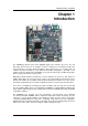
MANO870 Mini ITX Board Chapter 1 Introduction The MANO870 supports latest Intel rPGA998 CPU-socket interface processor, the 3rd ® ® ® Generation Intel Core i7 / i5 / i3 / Pentium / Celeron mobile processors which are built on 22 nm technologies to provide smart performance and responsiveness on executing tasks. It combines the CPU and GPU to offer fantastic HD media and graphics, especially on 3D gaming experience.
MANO870 Mini ITX Board 1.1 Features ® 1.2 ® TM ® ® i7 / i5 / i3 / Pentium / Celeron Specifications CPU rd rPGA988 socket G2 Intel 3 Generation Intel Core processors (Ivy Bridge) 2 DDR3 1333/1600MHz up to 16GB PCI-Express x16 Gen. 3 supported 4 USB 3.0 supported 2 SATA-600 supported TM CFast supported iAMT 8.0 supported TPM 1.2 supported Triple view display ® Intel ® Intel ® Intel ® Intel ® Intel TM Core i7 processor. TM Core i5 processor. TM Core i3 processor.
MANO870 Mini ITX Board Display One HDMI. One DVI-D One VGA One LVDS. Ethernet ® LAN1 – 10/100/1000Mbps, Intel 82579LM supports WOL, PXE. ® LAN2 – 10/100/1000Mbps, Intel 82583V supports WOL, PXE. Audio HD audio compliant (with MIC-in/line-out) via Realtek ALC892. Expansion Interface One PCI-Express x16 slot. One PCI-Express Mini Card Hardware Monitoring Detect CPU/system temperature, voltage and fan speed. Watchdog Timer 1~255 seconds; up to 256 levels.
MANO870 Mini ITX Board 1.
MANO870 Mini ITX Board Chapter 2 Board and Pin Assignments 2.1 Board Layout 2.
MANO870 Mini ITX Board 2.3 Jumper Settings Jumper is a small component consisting of jumper clip and jumper pins. Install jumper clip on 2 jumper pins to close. And remove jumper clip from 2 jumper pins to open. The following illustration shows how to set up jumper. Before applying power to MANO870 Series, please make sure all of the jumpers are in factory default position. Below you can find a summary table and onboard default settings.
MANO870 Mini ITX Board 2.3.1 Clear CMOS (JCMOS1) This jumper allows you to clear the Real Time Clock (RTC) RAM in CMOS. You can clear the CMOS memory of date, time, and system setup parameters by erasing the CMOS RTC RAM data. The onboard button cell battery powers the RAM data in CMOS, which includes system setup information such as system passwords. To erase the RTC RAM: 1. Turn OFF the computer and unplug the power cord. 2. Remove the onboard battery. 3.
MANO870 Mini ITX Board 2.3.4 COM2 RI/+5V/+12V Selection (JCOMPWR2) This jumper allows you to select the power mode of COM port 2. Function Setting +12V RI (Default) +5V 1-2 close 3-4 close 5-6 close 2.3.5 COM3 RI/+5V/+12V Selection (JCOMPWR3) This jumper allows you to select the power mode of COM port 3.
MANO870 Mini ITX Board 2.4 Connectors Signals go to other parts of the system through connectors. Loose or improper connection might cause problems, please make sure all connectors are properly and firmly connected. Here is a summary table which shows all connectors on the hardware. Connector Description KBMS PS/2 Keyboard and Mouse COM1 COM1 Connector DVI DVI Port VGA1 VGA Port HDMI1 HDMI Port LAN1USB12 LAN1, USB 3.0 Port 1 and 2 Connector LAN2USB34 LAN2, USB 3.
MANO870 Mini ITX Board 2.4.1 1. 2. 3. 4. 5. 6. 7. Rear Panel Connectors PS/2 mouse port (green). This port is for a PS/2 mouse. PS/2 keyboard port (purple). This port is for a PS/2 keyboard. Serial connector. This 9-pin COM1 port is for serial devices. HDMI port. This 19-pin HDMI 1.3 port connects to a HDMI monitor. VGA port. This 15-pin VGA port connects to a VGA monitor. DVI-D port. This 29-pin DVI-D port is for a DVI monitor. LAN (RJ-45) port.
MANO870 Mini ITX Board System fan interface is available through SYS_FAN1, see table below. Pin Signal 1 2 3 GND SYSFAN1_VCC(PWM) SYSFAN1_IO Caution 2.4.3 1 Do not forget to connect the fan cables to the fan connectors. Insufficient air flow inside the system may damage the motherboard components. These are not jumpers! DO NOT place jumper caps on the fan connectors. COM Connectors (COM2 and COM3) These connectors are for serial (COM) ports.
MANO870 Mini ITX Board 2.4.5 Front Panel Connector (F_PANEL1) This connector is for a chassis-mounted front panel I/O module that supports power on/reset switch and HDD/power LED indicate. Pin Signal 1 2 3 4 5 6 7 8 9 HDDLED+ POWERLED+HDDLEDPOWERLEDGND PWSWITCH RESET GND NC 1 ATX Power Button/Soft-off Button (Pin 6-8 PWRBT) This 2-pin connector is for the system power button. Pressing the power button turns the system on or puts the system in sleep or soft-off mode depending on the BIOS settings.
MANO870 Mini ITX Board 2.4.6 ATX Power Connectors (ATXPWR and ATX12V) Both connectors are for ATX power supply plugs. The power supply plugs are designed to fit these connectors in only one orientation. Find the proper orientation and push down firmly until the connectors completely fit.
MANO870 Mini ITX Board 2.4.7 Internal Audio Connector (FPAUD1) This connector is for a chassis-mounted front panel audio I/O module that supports either HD Audio or legacy AC ‘97 (optional) audio standard. Connect one end of the front panel audio I/O module cable to this connector.
MANO870 Mini ITX Board 2.4.9 LCD Inverter Connector (JBKL) The connector is for the control of internal LVDS brightness. Pin Signal 1 2 3 4 5 +12V GND ENBKL VR +5V 1 Signal Description: VR For inverter with adjustable backlight function, it is possible to control the LCD brightness through the VR signal. Vadj = 0.75V ~ 4.25V (Recommended: 4.7KΩ, >1/16W) ENBKL LCD backlight ON/OFF control signal 2.4.
MANO870 Mini ITX Board 2.4.11 SPI Connector (SPI_CN1) Is a point-to-point interface standard, which allows network equipment designers to develop an array of next-generation multi-service switches and routers to support multi-service traffic with aggregate bandwidths up to OC-192 (10Gb/s) and beyond, enabling them to dramatically increase system performance. Pin Signal 1 2 3 4 5 6 7 +3V GND SPI_CS# SPI_CLK SPI_MISO SPI_MOSI NC 2.4.
MANO870 Mini ITX Board 2.4.13 Serial ATA Connectors (SATA1~SATA5) These connectors (SATA1 and SATA2) support SATA 3.0 and are for the Serial ATA signal cables for Serial ATA hard disk drives. Pin Signal 1 2 3 4 5 6 7 GND SATA_TXP2 SATA_TXN2 GND SATA_RXN2 SATA_RXP2 GND SATA1, SATA2 These connectors (SATA3, SATA4 and SATA5) support SATA 2.0 and are for the Serial ATA signal cables for Serial ATA hard disk drives.
MANO870 Mini ITX Board This page is intentionally left blank.
MANO870 Mini ITX Board Chapter 3 Hardware Installation Take note of the following precautions before you install motherboard components or change any motherboard settings. Caution 3.1 Unplug the power cord from the wall socket before touching any component. Use a grounded wrist strap or touch a safely grounded object or a metal object, such as the power supply case, before handling components to avoid damaging them due to static electricity.
MANO870 Mini ITX Board Place this side towards the rear of the chassis. 3.2 Central Processing Unit (CPU) The motherboard comes with a surface mount FCPGA988 socket designed for the Intel Core™ i7/ i5/ i3 processor in the 988-land package. Important Caution 20 ® ® Your boxed Intel Core™ i7/ i5/ i3 mobile processor package should come with installation instructions for the CPU, fan and heatsink assembly.
MANO870 Mini ITX Board 3.2.1 1. Installing the CPU Locate the CPU socket on the motherboard. Before installing the CPU, make sure that the socket box is facing towards you and the load lever is on your left. Caution 2. Separate CPU cooler and its base first with screw driver. 3. Assemble the CPU fan retention module.
MANO870 Mini ITX Board 4. Position the CPU over the socket, making sure that the gold triangle is the same side as CPU socket triangle. CPU socket triangle 5. Turn the CPU lock clockwise to lock CPU. Caution 22 Gold triangle The CPU fits in only one correct orientation.
MANO870 Mini ITX Board 3.2.2 Installing the CPU Heatsink and Fan 1. 2. Place the heatsink base on the relative bottom of motherboard. Place the heatsink assembly on the top of the CPU, making sure that the four fasteners match the holes on the motherboard. 3. Screw tightly the four fasteners. 4. Connect the CPU fan cable to the connector on the motherboard labeled CPU_FAN. Do not forget to connect the CPU fan connector! Hardware monitoring errors can occur if you fail to plug this connector.
MANO870 Mini ITX Board 3.3 System Memory 3.3.1 Overview The motherboard comes with two 204-pin Double Data Rate 3 (DDR3) Small Outline Dual Inline Memory Modules (SO-DIMM) sockets. A DDR3 module has the same physical dimensions as a DDR SO-DIMM but has a 204-pin footprint compared to the 204-pin DDR2 DIMM. DDR3 DIMMs are notched differently to prevent installation on a DDR2 DIMM socket.
MANO870 Mini ITX Board 3.3.2 Memory Configurations You may install 1GB, 2GB, and 4GB unbuffered ECC or non-ECC DDR3 SO-DIMMs into the SO-DIMM sockets using the memory configurations in this section. Important 3.3.3 1. IF you installed four 1GB memory modules, the system may detect less than 3GB of total memory because of address space allocation for other critical functions.
MANO870 Mini ITX Board 2. Align a SO-DIMM on the socket such that the notch on the SO-DIMM matches the break on the socket. DDR3 SO-DIMM notch Unlocked retaining clip 3. Firmly insert the SO-DIMM into the socket until the retaining clips snap back in place and the SO-DIMM is properly seated. Locked retaining clip Important Caution 26 A DDR3 SO-DIMM is keyed with a notch so that it fits in only one direction. DO NOT force a SO-DIMM into a socket to avoid damaging the SO-DIMM.
MANO870 Mini ITX Board 3.3.4 1. 2. Removing a SO-DIMM Simultaneously press the retaining clips downward to unlock the SO-DIMM. Remove the SO-DIMM from the socket. Unlocked retaining clip Note 3.4 Support the SO-DIMM lightly with your fingers when pressing the retaining clips. The SO-DIMM might get damaged when it flips out with extra force. Expansion Card In the future, you may need to install expansion cards. The following sub-sections describe the slots and the expansion cards that they support.
MANO870 Mini ITX Board 3.4.2 Configuring an Expansion Card After installing the expansion card, configure it by adjusting the software settings. 1. Turn on the system and change the necessary BIOS settings, if any. See Chapter 5 for information on BIOS setup. 2. Assign an IRQ to the card if needed. 3. Install the software drivers for the expansion card. 3.4.3 PCI-Express x16 Slot This motherboard supports one PCI-Express x16.
MANO870 Mini ITX Board 3.4.5 CFastTM Socket TM This motherboard supports one CFast card socket and its location is on bottom side of TM TM the PCB. The following figure shows a CFast card installed on the CFast socket.
MANO870 Mini ITX Board This page is intentionally left blank.
MANO870 Mini ITX Board Chapter 4 Hardware Description 4.1 Microprocessors ® TM TM TM ® ® The MANO870 Series supports Intel Core i7 / Core i5 / Core i3 / Pentium / Celeron ® ® processors, which enable your system to operate under Windows XP, Windows 7 and Linux environments. The system performance depends on the microprocessor. Make sure all correct settings are arranged for your installed microprocessor to prevent the CPU from damages. 4.
MANO870 Mini ITX Board 4.4 I/O Port Address Map ® TM TM TM ® ® The Intel Core i7 / Core i5 / Core i3 / Pentium / Celeron processors communicate via I/O ports. Total 1KB port addresses are available for assigning to other devices via I/O expansion cards.
MANO870 Mini ITX Board Hardware Description 33
MANO870 Mini ITX Board 4.
MANO870 Mini ITX Board Hardware Description 35
MANO870 Mini ITX Board 4.
MANO870 Mini ITX Board Chapter 5 AMI BIOS Setup Utility The AMI UEFI BIOS provides users with a built-in setup program to modify basic system configuration. All configured parameters are stored in a flash chip to save the setup information whenever the power is turned off. This chapter provides users with detailed description about how to set up basic system configuration through the AMI BIOS setup utility. 5.1 Starting To enter the setup screens, follow the steps below: 1. 2.
MANO870 Mini ITX Board Hot Keys Description Left/Right The Left and Right keys allow you to select a setup screen. Up/Down The Up and Down keys allow you to select a setup screen or sub-screen. + Plus/Minus The Plus and Minus keys allow you to change the field value of a particular setup item. Tab The key allows you to select setup fields. F1 The key allows you to display the General Help screen. F2 The key allows you to Load Previous Values.
MANO870 Mini ITX Board 5.3 Main Menu When you first enter the setup utility, you will enter the Main setup screen. You can always return to the Main setup screen by selecting the Main tab. System Time/Date can be set up as described below. The Main BIOS setup screen is shown below. BIOS Information Display the auto-detected BIOS information. System Date/Time Use this option to change the system time and date. Highlight System Time or System Date using the keys.
MANO870 Mini ITX Board 5.4 Advanced Menu The Advanced menu also allows users to set configuration of the CPU and other system devices.
MANO870 Mini ITX Board PCI Subsystem Settings You can use this screen to select options for PCI subsystem settings, and change the value of the selected option. A description of the selected item appears on the right side of the screen. PCI Bus Driver Version Display the information of PCI bus driver version. Above 4G Decoding Enable or disable 64-bit capable devices to be decoded in above 4G address space. PCI Latency Timer Allow the PCI latency timer to be adjusted.
MANO870 Mini ITX Board ACPI Settings You can use this screen to select options for the ACPI configuration, and change the value of the selected option. A description of the selected item appears on the right side of the screen. ACPI Sleep State Select the highest ACPI sleep state the system will enter when the suspend button is pressed. Configuration options are Suspend Disabled, S1 only (CPU Stop Clock), and S3 only (Suspend to RAM).
MANO870 Mini ITX Board Trusted Computing This screen provides function for specifying the Trusted Platform Module (TPM) settings. TPM Support Enable or disable TPM support. TPM State Specify whether TPM can be used by the operating system. Pending Operation Schedule a TPM operation which will be performed during the next boot process. Current Status Information Display current TPM status information.
MANO870 Mini ITX Board CPU Configuration This screen shows the CPU information. Hyper-threading Use this item to enable or disable Hyper-Threading Technology, which makes a single physical processor perform multi-tasking function as two logical ones. Active Processor Cores Allow users to set how many processor cores should be active.
MANO870 Mini ITX Board SATA Configuration In this Configuration menu, you can see the currently installed hardware in the SATA ports. During system boot up, the BIOS automatically detects the presence of SATA devices. SATA Controller(s) Enable or disable SATA device. SATA Mode Selection Determine how SATA controller(s) operate. Operation mode options are: IDE Mode, AHCI Mode and RAID Mode.
MANO870 Mini ITX Board Intel TXT(LT) Configuration ® This screen displays Intel Trusted Execution Technology (TXT) configuration. PCH-FW Configuration This screen displays Management Engine (ME) Firmware information.
MANO870 Mini ITX Board AMT Configuration Use this screen to configure AMT parameters. Intel AMT ® Enable or disable Intel Active Management Technology BIOS Extension. Un-Configure ME Un-configure ME without password.
MANO870 Mini ITX Board USB Configuration You can use this screen to select options for the USB Configuration, and change the value of the selected option. A description of the selected item appears on the right side of the screen. USB Devices Display all detected USB devices. Legacy USB Support Use this item to enable or disable support for USB device on legacy operating system. The default setting is Enabled. Auto option disables legacy support if no USB devices are connected.
MANO870 Mini ITX Board Second Super IO Configuration You can use this screen to select options for the Second Super IO Configuration, and change the value of the selected option. A description of the selected item appears on the right side of the screen. For items marked with “”, please press for more options. Serial Port 2 and 3 Configuration Use this item to set parameters of serial port 2 and 3.
MANO870 Mini ITX Board Super IO Configuration You can use this screen to select options for the Super IO Configuration, and change the value of the selected option. A description of the selected item appears on the right side of the screen. For items marked with “”, please press for more options. Serial Port 1 Configuration Use this item to set parameters of serial port 1. Resume on PS2 KB/MS Enable or disable resume on PS/2 keyboard and mouse function.
MANO870 Mini ITX Board H/W Monitor Use this screen for Smart Fan configuration and hardware health status monitoring. This screen displays the temperature of system and CPU, cooling fan speed in RPM and system voltages (VCORE, +12V, +5V, 5VSB, etc). Smart Fan This option allows users to configure Smart Fan function.
MANO870 Mini ITX Board Option Rom Policy Boot Option Filter This option controls what devices system can boot to. Launch PXE OpROM policy Enable or disable boot options for legacy network devices. Launch Storage OpROM policy Control the execution of UEFI and legacy storage OpROM.
MANO870 Mini ITX Board CPU PPM Configuration Use this screen for CPU PPM configuration. EIST ® Enable or disable Intel SpeedStep. When enabled, CPU speed is controlled by the operating system. When disabled, CPU runs at its default speed. Turbo Mode This item is for enabling or disabling turbo mode. When enabled, it allows processor cores to run faster than marked frequency under certain conditions.
MANO870 Mini ITX Board 5.5 Chipset Menu The Chipset menu allows users to change the advanced chipset settings. You can select any of the items in the left frame of the screen to go to the sub menus: ► PCH-IO Configuration ► System Agent (SA) Configuration For items marked with “”, please press for more options.
MANO870 Mini ITX Board PCH-IO Configuration This screen allows users to set PCH parameters. LAN1 Controller Enable or disable LAN1 controller. Wake on LAN1 Enable or disable Wake on LAN1 functionality. LAN2 Controller Enable or disable LAN2 controller. Restore AC Power Loss Set the system power status when power returns from a power failure situation. The system power status options are Power Off, Power On and Last State.
MANO870 Mini ITX Board PCH USB Configuration USB3.0 Support Enable or disable the XHCI controller for USB 3.0. EHCI1/EHCI2 Enable or disable the EHCI controller. USB Ports Per-Port Disable Control Enable or disable each USB port individually.
MANO870 Mini ITX Board PCH Azalia Configuration Azalia Control detection of the Azalia device. Configuration options are Disabled, Enabled and Auto.
MANO870 Mini ITX Board System Agent (SA) Configuration This screen shows System Agent information and provides function for specifying related parameters. For items marked with “”, please press for more options. VT-d ® Enable or disable Intel chipset virtualization technology for directed I/O. VT-d can help end users improve security and reliability of the systems and also improve performance of I/O devices in virtualized environment.
MANO870 Mini ITX Board Graphics Configuration Primary Display Allow you to select which graphics controller to use as the primary boot device. Internal Graphics Enable or disable IGD. DVMT Pre-Allocated Select DVMT pre-allocated memory size. DVMT Total Gfx Mem Select DVMT total memory size.
MANO870 Mini ITX Board LCD Control Primary IGFX Boot Display Allow you to select the display device which will be activated during POST. This has no effect if external graphics present. Secondary boot display selection will appear based on your selection. Configuration options are CRT, DVI, LVDS and HDMI. Secondary IGFX Boot Display Allow you to select secondary display device. Secondary IGFX boot display options are: CRT, DVI, LVDS and HDMI.
MANO870 Mini ITX Board NB PCIe Configuration PEG0 – Gen X Select PEG0 speed. PEG0 ASPM Control ASPM support for the PEG device. Enable PEG Enable or disable PEG always.
MANO870 Mini ITX Board 62 Memory Configuration This screen displays system memory information.
MANO870 Mini ITX Board 5.6 Boot Menu The Boot menu allows users to change boot options of the system. Setup Prompt Timeout Number of seconds to wait for setup activation key. 65535(0xFFFF) means indefinite waiting. Bootup NumLock State Use this item to select the power-on state for the keyboard NumLock. Quiet Boot Select to display either POST output messages or a splash screen during boot-up. Boot Option Priorities These are settings for boot priority.
MANO870 Mini ITX Board 5.7 Security Menu The Security menu allows users to change the security settings for the system. Administrator Password This item indicates whether an administrator password has been set (installed or uninstalled). User Password This item indicates whether an user password has been set (installed or uninstalled).
MANO870 Mini ITX Board 5.8 Save & Exit Menu The Save & Exit menu allows users to load your system configuration with optimal or fail-safe default values. Save Changes and Exit When you have completed the system configuration changes, select this option to leave Setup and return to Main Menu. Select Save Changes and Exit from the Save & Exit menu and press . Select Yes to save changes and exit.
MANO870 Mini ITX Board This page is intentionally left blank.