SBC86822 Series ® ® Intel Pentium M All-In-One Mini ITX CPU Board With DualView Display and SATA User’s Manual
Disclaimers This manual has been carefully checked and believed to contain accurate information. AXIOMTEK Co., Ltd. assumes no responsibility for any infringements of patents or any third party’s rights, and any liability arising from such use. AXIOMTEK does not warrant or assume any legal liability or responsibility for the accuracy, completeness or usefulness of any information in this document. AXIOMTEK does not make any commitment to update the information in this manual.
ESD Precautions Computer boards have integrated circuits sensitive to static electricity. To prevent chipsets from electrostatic discharge damage, please take care of the following jobs with precautions: Do not remove boards or integrated circuits from their anti-static packaging until you are ready to install them. Before holding the board or integrated circuit, touch an unpainted portion of the system unit chassis for a few seconds. It discharges static electricity from your body.
Table of Contents Disclaimers ........................................................................................................... ii ESD Precautions ................................................................................................. iii Chapter 1 Introduction .................................................................... 1 1.1 1.2 Specifications .......................................................................................... 2 Utilities Supported .....................
3.4 3.5 I/O Port Address Map............................................................................ 42 Interrupt Controller ................................................................................ 43 Chapter 4 Award BIOS Utility ....................................................... 45 4.1 4.2 4.3 4.4 4.5 4.6 4.7 4.8 4.9 4.10 4.11 4.12 4.13 4.14 4.15 4.16 Entering Setup....................................................................................... 45 Control Keys ...................
MEMO vi
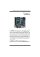
SBC86822 Series All-In-One Mini ITX Board User’s Manual Chapter 1 Introduction ® ® The SBC86822, a Mini ITX CPU board, supports Intel Pentium M/ ® Celeron M processors with graphics, audio, and Gigabit Ethernet ® ® interfaces. It is practically finest embedded Pentium M/ Celeron M board in the market. It integrates LPC I/Os, UXGA, LCD, Ethernet and audio to make all in one single board.
SBC86822 Series All-In-One Mini ITX Board User’s Manual 1.
SBC86822 Series All-In-One Mini ITX Board User’s Manual z USB Interface Eight USB ports with fuse protection and complies with USB Spec. Rev. 2.0 z Watchdog Timer 1~255 seconds; up to 255 levels z Graphics Intel 910GMLE GMCH Gen 3.
SBC86822 Series All-In-One Mini ITX Board User’s Manual 1.
SBC86822 Series All-In-One Mini ITX Board User’s Manual Chapter 2 Jumpers and Connectors 2.
SBC86822 Series All-In-One Mini ITX Board User’s Manual Solder Side 6 Jumpers and Connectors
SBC86822 Series All-In-One Mini ITX Board User’s Manual 2.
SBC86822 Series All-In-One Mini ITX Board User’s Manual Solder Side 8 Jumpers and Connectors
SBC86822 Series All-In-One Mini ITX Board User’s Manual 2.3 Jumper Settings Proper jumer settings configure the SBC86822 to meet your application purpose. We are herewith listing a summary table of all jumpers and default settings for onboard devices, respectively.
SBC86822 Series All-In-One Mini ITX Board User’s Manual NOTICE 1 COM1COM2 is a built-in connector for COM1 and COM2 ports. NOTICE 2 COM2 connectors are COLAY to and CN3 connectors. 2.3.1 COM1~COM6 Mode Select for Type Jumpers (JP1, JP2, JP3, JP16, JP15, JP14) These jumpers select the COM1~COM6 ports’ DCD and RI mode.
SBC86822 Series All-In-One Mini ITX Board User’s Manual Description CN3(COM2) Function Jumper Setting Pin 1=5V Pin 1=12V JP2 JP2 JP2 *Pin 1=DCD JP2 Pin 8=5V JP2 Pin 8=12V *Pin 8=RI Jumpers and Connectors JP2 JP2 JP2 11
SBC86822 Series All-In-One Mini ITX Board User’s Manual Description COM2 Function Pin 1=5V Pin 1=12V JP2 JP2 JP2 *Pin 1=DCD JP2 Pin 9=5V JP2 Pin 9=12V *Pin 9=RI 12 Jumper Setting JP2 JP2 JP2 Jumpers and Connectors
SBC86822 Series All-In-One Mini ITX Board User’s Manual Description COM3 Function Jumper Setting Pin 1=5V Pin 1=12V JP3 JP3 JP3 *Pin 1=DCD JP3 Pin 9=5V JP3 Pin 9=12V *Pin 9=RI Jumpers and Connectors JP3 JP3 JP3 13
SBC86822 Series All-In-One Mini ITX Board User’s Manual Description COM4 (CN13) Function Pin 1=5V Pin 1=12V JP16 JP16 JP16 *Pin 1=DCD JP16 Pin 8=5V JP16 Pin 8=12V *Pin 8=RI 14 Jumper Setting JP16 JP16 JP16 Jumpers and Connectors
SBC86822 Series All-In-One Mini ITX Board User’s Manual Description COM5 (CN14) Function Jumper Setting Pin 1=5V Pin 1=12V JP15 JP15 JP15 *Pin 1=DCD JP15 Pin 8=5V JP15 Pin 8=12V *Pin 8=RI Jumpers and Connectors JP15 JP15 JP15 15
SBC86822 Series All-In-One Mini ITX Board User’s Manual Description COM6 (CN15) Function Pin 1=5V Pin 1=12V JP14 JP14 JP14 *Pin 1=DCD JP14 Pin 8=5V JP14 Pin 8=12V *Pin 8=RI 16 Jumper Setting JP14 JP14 JP14 Jumpers and Connectors
SBC86822 Series All-In-One Mini ITX Board User’s Manual 2.3.2 CPU Analog Voltage Select Jumper (JP4) Use this jumper to select the CPU analog voltage. Description CPU Analog Voltage Select Function Dothan 1.5V (Default) Banias 1.8V 2.3.3 Jumper Setting JP4 JP4 Flat Panel Connector Voltage Selection Jumper (JP5, JP6) The board supports +3.3V or +5V flat panel displays. Configure the jumper JP6 to the appropriate voltage of the flat panel (LVDS1).
SBC86822 Series All-In-One Mini ITX Board User’s Manual The board supports +3.3V or +5V flat panel displays. Configure the jumper JP5 to the appropriate voltage of the flat panel (LVDS2). Description Flat Panel Connector (LVDS2) Voltage Selection 2.3.4 Function Jumper Setting 3.3V (Default) JP5 5V JP5 USB Power Select Jumpers (JP7, JP11, JP12, JP13) This jumper is to select the voltage for USB interface.
SBC86822 Series All-In-One Mini ITX Board User’s Manual Description USB4 Connector (CN12) Voltage Selection Function 5V_SBY (Default) JP11 5V JP11 Description USB1 Connector (CN8) Voltage Selection Function Jumper Setting 5V_SBY (Default) JP12 5V JP12 Description USB2 Connector (CN11) Voltage Selection Jumper Setting Function Jumper Setting 5V_SBY (Default) JP13 5V JP13 Jumpers and Connectors 19
SBC86822 Series All-In-One Mini ITX Board User’s Manual 2.3.5 CPU Clock Select Jumper (JP8) Use this jumper to select the CPU clock. Description Function CPU Clock Select Auto (Default) 2.3.6 Jumper Setting JP8 100 MHz JP8 133 MHz JP8 TPM PP (Physical Presence) Select Jumper (JP10) Description Function TPM PP (Physical Accept both Presence) Select H/W & S/W signals. (Default) Only Accept H/W signals. Jumper Setting JP10 JP10 It is an optional jumper, not mounted as a default design.
SBC86822 Series All-In-One Mini ITX Board User’s Manual 2.3.7 CMOS Clear Jumper (JP17) You may need to use this jumper is to clear the CMOS memory if incorrect settings in the Setup Utility. Description CMOS Clear 2.3.8 Function Jumper Setting Normal (Default) JP17 Clear CMOS JP17 CompactFlash Setting Jumper (JP18)(Optional) Use this jumper to set Master/Slave Compact Flash interface.
SBC86822 Series All-In-One Mini ITX Board User’s Manual 2.3.9 CompactFlash™ Power Selection Jumper (JP19) This jumper is to select the voltage for CompactFlash™ interface. Description CompactFlash™ Power Select Function Jumper Setting 3.3V (Default) JP19 5V JP19 2.3.10 Audio Output Jumper (JP20) This jumper makes the selection of Audio output.
SBC86822 Series All-In-One Mini ITX Board User’s Manual 2.3.11 CN2, CN25 Keyboard/Mouse application Jumper (JP21) This jumper makes the selection of Keyboard/Mouse application.
SBC86822 Series All-In-One Mini ITX Board User’s Manual Application 2: 24 Jumpers and Connectors
SBC86822 Series All-In-One Mini ITX Board User’s Manual 2.4 Connectors Connectors connect the CPU card with other parts of the system. Loose or improper connection might cause problems. Make sure all connectors are properly and firmly connected. Here is a summary table shows you all connectors on the SBC86822 Series.
SBC86822 Series All-In-One Mini ITX Board User’s Manual 2.4.
SBC86822 Series All-In-One Mini ITX Board User’s Manual 2.4.2 Keyboard and PS/2 Connector (CN2) The SBC86822 provides a keyboard and Mouse interface with a DIN connector.To install the PS/2 keyboard and mouse, plug the mouse to the upper port (green), and the keyboard to the lower port (purple).
SBC86822 Series All-In-One Mini ITX Board User’s Manual JP21 Application 1: Pin Signal 1 K/B Data 2 K/B CLK 3 GND 4 +5V 5 M/S Data 6 M/S CLK CN25 JP21 Application 2: Pin 28 Signal 1 K/B Data 2 K/B CLK 3 GND 4 +5V 5 External K/B Data 6 External K/B CLK CN25 Jumpers and Connectors
SBC86822 Series All-In-One Mini ITX Board User’s Manual 2.4.3 LVDS1/LVDS2 (Optional) Backlight Connectors (CN6, CN4) The CN6 and CN4 are DF13-7S-1.25C 7-pin connectors for inverter that we strongly recommend you to use the matching DF13-7S-1.25C connector. Pin 1 2 3 4 5 6 7 2.4.4 Signal +12V +12V +5V ENABLE GND GND GND CN6/CN4 LVDS1/LVDS2 (Optional) Flat Panel Connectors (CN5, CN7) The LVDS connector on the SBC is a 40-pin connector.
SBC86822 Series All-In-One Mini ITX Board User’s Manual 2.4.5 USB1/USB2 Connectors (CN8, CN11) These Universal Serial Bus (USB) connectors on this board are for installing versatile USB interface peripherals. These are 10-pin standard USB connectors.
SBC86822 Series All-In-One Mini ITX Board User’s Manual Pin 1 2 3 4 5 6 7 8 A B Signal CN9A/CN12A MDI0+ MDI0MDI1+ MDI1MDI2+ MDI2MDI3+ MDI3100 LAN LED (Green)/ 1000 LAN LED (Orange) Active LED (Orange) Pin Signal 1 +5V 2 USB D4- 3 USB D4+ 4 GND 5 +5V 6 USB D5- 7 USB D5+ 8 GND Pin Signal 1 +5V 2 USB D6- 3 USB D6+ 4 GND 5 +5V 6 USB D7- 7 USB D7+ 8 GND Jumpers and Connectors CN9B CN12B 31
SBC86822 Series All-In-One Mini ITX Board User’s Manual 2.4.7 ATX Power Connector (CN10) Steady and sufficient power can be supplied to all components on the board by connecting the power connector. Please make sure all components and devices are properly installed before connecting the power connector. Align the power connector with its proper location on the board, and connect it tightly.
SBC86822 Series All-In-One Mini ITX Board User’s Manual 2.4.9 Audio Phone Jack Connector (CN18) After install onboard audio driver, you may connect speaker to Line Out jack, microphone to MIC in jack. Pin 1 2 3 4 5 6 7 8 9 Signal CN18 Ground (GND) VREFOUT N.C Ground (GND) MIC_IN LINE_OUT_L LINE_OUT_L1 LINE_OUT_R1 LINE_OUT_R 2.4.10 Internal Audio Connector (CN19) The SBC86822 supports internal audio interface. CN19 is a 5pinheader connector commonly used for the audio.
SBC86822 Series All-In-One Mini ITX Board User’s Manual 2.4.11 Enhanced IDE Interface Connector (CN20) There are three built-in IDE channels, one parallel ATA-100 and two serial ATA-150, which support up to four IDE devices. CN20 is a 40-pin IDE interface connector for standard 3.5” IDE device.
SBC86822 Series All-In-One Mini ITX Board User’s Manual You can enter the BIOS CMOS Setup Utility to configure the address selection of onboard parallel port, CN21 (378H) or Disabled.
SBC86822 Series All-In-One Mini ITX Board User’s Manual Pin Signal Pin Signal 1 Digital Input 0 2 Digital Output 0 3 Digital Input 1 4 Digital Output 1 5 Digital Input 2 6 Digital Output 2 7 Digital Input 3 8 Digital Output 3 9 Ground (GND) 10 Ground (GND) CN22 Digital Input Address:402A Digital Output Bit7 X Bit6 X Bit5 DI3 Digital Input Bit4 DI2 Bit3 DI1 Bit2 DI0 Bit4 X Bit3 DO3 Bit2 DO2 Bit1 X Bit0 X Digital Output : Digital Output Bit7 X Bit6 X Bit5 X Digital Inpu
SBC86822 Series All-In-One Mini ITX Board User’s Manual External Speaker and Internal Buzzer Connector Pin 2, 4, 6 and 8 can be connected to the case-mounted speaker unit or internal buzzer. While connecting the CPU card to an internal buzzer, please short pins 2-4; while connecting to an external speaker, you need to set pins 2-4 to Open and connect the speaker cable to pin 8 (+) and pin 2 (-).
SBC86822 Series All-In-One Mini ITX Board User’s Manual Pin Signal Pin Signal 4 Data 5 29 Data 13 5 Data 6 30 Data 14 6 Data 7 31 Data 15 7 CS0# 32 CS1# 8 Address 10 33 VS1# 9 ATASEL 34 IORD# 10 Address 9 35 IOWR# 11 Address 8 36 WE# 12 Address 7 37 INTR 13 VCC 38 VCC 14 Address 6 39 CSEL# 15 Address 5 40 VS2# 16 Address 4 41 RESET# 17 Address 3 42 IORDY# 18 Address 2 43 DMAREQ 19 Address 1 44 DMAACK- 20 Address 0 45 DASP# 21 Data 0 4
SBC86822 Series All-In-One Mini ITX Board User’s Manual 2.4.16 VGA Connector (VCOM3B) VCOM3B is a standard 15-pin DB15 connector commonly for the CRT VGA display. Pin Signal 1 2 3 4 5 6 Red Green Blue N.C Ground (GND) AnalogGround(AGND) 7 AnalogGround(AGND) 8 AnalogGround(AGND) 9 10 11 12 13 14 15 N.C Ground (GND) N.C DDC DATA Horizontal Sync Vertical Sync DDC CLK VCOM3B 2.4.17 CPU and System Fan Connectors (FAN1, FAN2) FAN1 and FAN2 are CPU and System FAN Connectors.
SBC86822 Series All-In-One Mini ITX Board User’s Manual 2.4.18 SMBUS Connectors (CN24) Connector CN24 is for SMBUS interface support.
SBC86822 Series All-In-One Mini ITX Board User’s Manual Chapter 3 Hardware Description 3.1 Microprocessors ® ® ® The SBC86822 Series supports Intel Pentium M/Celeron M processors, which make your system operated under Windows 2000/XP and Linux environments. The system performance depends on the microprocessor. Make sure your installed microprocessor with all correct settings that prevents the CPU from damages. 3.
SBC86822 Series All-In-One Mini ITX Board User’s Manual 3.4 I/O Port Address Map ® ® ® The Intel Pentium M/Celeron M CPUs can communicate via I/O ports. There are total 1KB port addresses available for assignment to other devices via I/O expansion cards.
SBC86822 Series All-In-One Mini ITX Board User’s Manual 3.5 Interrupt Controller The SBC86822 Series is a 100% PC compatible control board. It consists of 16 interrupt request lines, and four out of them can be programmable. The mapping list of the 16 interrupt request lines is shown as the following table.
SBC86822 Series All-In-One Mini ITX Board User’s Manual MEMO 44 Hardware Description
SBC86822 Series All-In-One Mini ITX Board User’s Manual Chapter 4 Award BIOS Utility The Phoenix-Award BIOS provides users with a built-in Setup program to modify basic system configuration. All configured parameters are stored in a battery-backed-up RAM (CMOS RAM) to save the Setup information whenever the power is turned off. 4.1 Entering Setup There are two ways to enter the Setup program.
SBC86822 Series All-In-One Mini ITX Board User’s Manual 4.
SBC86822 Series All-In-One Mini ITX Board User’s Manual 4.4 The Main Menu Once you enter the Award BIOS CMOS Setup Utility, the Main Menu will appear on the screen. The Main Menu allows you to select from ten setup functions and two exit choices. Use the arrow keys to select the setup function you intend to configure then press to accept or enter its sub-menu.
SBC86822 Series All-In-One Mini ITX Board User’s Manual 4.5 Standard CMOS Setup Menu The items in Standard CMOS Setup Menu are divided into 10 categories. Each category includes no, one or more than one setup items. Use the arrow keys to highlight the item and then use the or keys to select the value you want in each item. z Date The date format is , . Press to show the calendar.
SBC86822 Series All-In-One Mini ITX Board User’s Manual z IDE Channel 0/1 Master / IDE Channel 0/1 Slave The categories identify the types of one channel that have been installed in the computer. There are 45 predefined types and 2 users definable types are for Enhanced IDE BIOS. Type 1 to Type 45 is predefined. Type User is user-definable. Press /<+> or /<−> to select a numbered hard disk type or type the number and press .
SBC86822 Series All-In-One Mini ITX Board User’s Manual Press to return to the Main Menu page. 4.6 Advanced BIOS Features This section allows you to configure and improve your system and allows you to set up some system features according to your preference.
SBC86822 Series All-In-One Mini ITX Board User’s Manual z Hard Disk Boot Priority Scroll to this item and press to view the sub menu to decide the disk boot priority. Press to return to the Advanced BIOS Features page. z Virus Warning This option flashes on the screen. During and after the system boot up, any attempt to write to the boot sector or partition table of the hard disk drive will halt the system with the following message. You can run an anti-virus program to locate the problem.
SBC86822 Series All-In-One Mini ITX Board User’s Manual Enabled Disabled It automatically activates while the system boots up and a warning message appears for an attempt to access the boot sector or hard disk partition table. No warning message will appear for attempts to access the boot sector or hard disk partition table. NOTE This function is only available with DOS and other operating systems that do not trap INT13. z CPU L1 & L2 Cache These two options speed up memory access.
SBC86822 Series All-In-One Mini ITX Board User’s Manual z Boot Up NumLock Status Selects power on state for NumLock. The default value is “On”. z Gate A20 Option The default value is “Fast”. z Normal The A20 signal is controlled by keyboard controller or chipset hardware. Fast Default: Fast. The A20 signal is controlled by Port 92 or chipset specific method. Typematic Rate Setting This determines the typematic rate of the keyboard. The default value is “Disabled”.
SBC86822 Series All-In-One Mini ITX Board User’s Manual z Typematic Delay (Msec) This option sets the display time interval from the first to the second character when holding a key. The default value is “250”. 250 500 750 1000 z 250 msec 500 msec 750 msec 1000 msec Security Option This item allows you to limit access to the system and Setup, or just to Setup. The default value is “Setup”.
SBC86822 Series All-In-One Mini ITX Board User’s Manual 4.7 Advanced Chipset Features Since the features in this section are related to the chipset on the CPU board and are completely optimized, you are not recommended to change the default settings in this setup table unless you are well oriented with the chipset features. z DRAM Timing Selectable Use this item to increase the timing of the memory. This is related to the cooling of memory.
SBC86822 Series All-In-One Mini ITX Board User’s Manual CAS and RAS strobe signals, used when DRAM is written to, read from, or refreshed. z DRAM RAS# Precharge The precharge time is the number of cycles it takes for the RAS to accumulate its charge before DRAM refresh. If insufficient time is allowed, refresh may be incomplete and the DRAM may fail to retain data. z Precharge Delay The precharge time is the number of cycles it takes for DRAM to accumulate its charge before refresh.
SBC86822 Series All-In-One Mini ITX Board User’s Manual z DVMT/Fixed Memory Size DVMT (Dynamic Video Memory Technology) allows you to select a maximum size of dynamic amount usage of the video memory. The system would configure the video memory dependent on your application. z Boot Display This item is to select Display Device that the screen will be shown.
SBC86822 Series All-In-One Mini ITX Board User’s Manual z OnChip IDE Device Scroll to this item and press to view the sub menu OnChip IDE Device. ¾ ¾ ¾ 58 IDE HDD Block Mode Block mode is also called block transfer, multiple commands, or multiple sector read/write. If your IDE hard drive supports block mode (most new drives do), select Enabled for automatic detection of the optimal number of block read/writes per sector the drive can support.
SBC86822 Series All-In-One Mini ITX Board User’s Manual ¾ ¾ NOTE Choosing Disabled for these options willautomatically remove the IDE rimaryMaster/Slave PIO and/or IDE Secondary Master/Slave PIO items on the menu. IDE Master/Slave PIO The four IDE PIO (Programmed Input/Output) fields let you set a PIO mode (0-4) for each of the four IDE devices that the onboard IDE interface supports. Modes 0 to 4 provide successively increased performance.
SBC86822 Series All-In-One Mini ITX Board User’s Manual z Onboard Device Scroll to this item and press to view the sub menu Onboard Device. ¾ ¾ ¾ USB Controller Enable this item if you are using the USB in the system. You should disable this item if a higher-level controller is added. USB 2.0 Controller Enable this item if you are using the EHCI (USB2.0) controller in the system. AC’97 Audio Select Use this item to enable or disable the onboard AC’97 Audio function.
SBC86822 Series All-In-One Mini ITX Board User’s Manual z Super IO Device Scroll to this item and press to view the sub menu Super IO Device. ¾ ¾ ¾ ¾ ¾ Onboard Serial Port 1/2/3/4/5/6 Select an address and corresponding interrupt for the serial port. Options: 3F8/IRQ4, 2E8/IRQ3, 3E8/IRQ4, 2E8/IRQ3, 3F0/IRQ4, 2E0/IRQ3, Disabled. Onboard Paralellel Port This item allows you to determine access onboard parallel port controller with which I/O address.
SBC86822 Series All-In-One Mini ITX Board User’s Manual ¾ PWRON After PWR-Fail This item enables your computer to automatically restart or return to its operating status. Press to return to the Integrated Peripherals page, and press it again to the Main Menu page. 4.9 Power Management Setup The Power Management Setup allows you to save energy of your system effectively. It will shut down the hard disk and turn OFF video display after a period of inactivity.
SBC86822 Series All-In-One Mini ITX Board User’s Manual Standby mode in S1 (POS) or S3 (STR) fashion through the setting of this field. Options are: [S1(POS)] The S1 sleep mode is a low power state. In this state, no system context is lost (CPU or chipset) and hardware maintains all system context.
SBC86822 Series All-In-One Mini ITX Board User’s Manual z Suspend Mode After the selected period of system inactivity (1 minute to 1 hour), all devices except the CPU shut off. The default value is “Disabled”. Disabled 1/2/4/6/8/10/2 0/30/40 Min/1 Hr System will never enter SUSPEND mode Defines the continuous idle time before the system entering SUSPEND mode.
SBC86822 Series All-In-One Mini ITX Board User’s Manual 4.10 PnP/PCI Configuration Setup This section describes configuring the PCI bus system. PCI, or Personal Computer Interconnect, is a system which allows I/O devices to operate at speeds nearing the speed the CPU itself uses when communicating with its own special components. This section covers some very technical items and it is strongly recommended that only experienced users should make any changes to the default settings.
SBC86822 Series All-In-One Mini ITX Board User’s Manual value is “Manual”. z IRQ Resources When resources are controlled manually, assign each system interrupt to one of the following types in accordance with the type of devices using the interrupt: 1. 2. Legacy ISA Devices compliant with the original PC AT bus specification, requiring a specific interrupt (such as IRQ4 for serial port 1). PCI/ISA PnP Devices compliant with the Plug and Play standard, whether designed for PCI or ISA bus architecture.
SBC86822 Series All-In-One Mini ITX Board User’s Manual 4.11 PC Health Status This section supports hardware monitering that lets you monitor those parameters for critical voltages, temperatures and fan speed of the board. z Shutdown Temperature It helps you set the maximum temperature they system can reach before powering down. z Current SYSTEM Temperature Show you the current system temperature.
SBC86822 Series All-In-One Mini ITX Board User’s Manual monitored by the hardware monitoring IC. Press to return to the Main Menu page. 4.12 Frequency/Voltage Control This section is to control the CPU frequency and Supply Voltage, DIMM OverVoltage and AGP voltage. z Auto Detect PCI Clk The enabled item can automatically disable the clock source for a PCI slot which does not have a module in it, reducing EMI (ElectroMagnetic Interference).
SBC86822 Series All-In-One Mini ITX Board User’s Manual 4.13 Load Optimized Defaults This option allows you to load the default values to your system configuration. These default settings are optimal and enable all high performance features. To load SETUP defaults value to CMOS SRAM, enter “Y”. If not, enter “N”.
SBC86822 Series All-In-One Mini ITX Board User’s Manual 4.14 Set Supervisor/User Password You can set a supervisor or user password, or both of them. The differences between them are: 1. 2. Supervisor password: You can enter and change the options on the setup menu. User password: You can just enter, but have no right to change the options on the setup menu. When you select this function, the following message will appear at the center of the screen to assist you in creating a password.
SBC86822 Series All-In-One Mini ITX Board User’s Manual 4.15 Save & Exit Setup This allows you to determine whether or not to accept the modifications. Typing “Y” quits the setup utility and saves all changes into the CMOS memory. Typing “N” brigs you back to Setup utility.
SBC86822 Series All-In-One Mini ITX Board User’s Manual 4.16 Exit Without Saving Select this option to exit the Setup utility without saving the changes you have made in this session. Typing “Y” will quit the Setup utility without saving the modifications. Typing “N” will return you to Setup utility.
SBC86822 Series All-In-One Mini ITX Board User’s Manual AppendixA Watchdog Timer Watchdog Timer Setting After the system stops working for a while, it can be auto-reset by the Watchdog Timer. The integrated Watchdog Timer can be set up in the system reset mode by program.
SBC86822 Series All-In-One Mini ITX Board User’s Manual z z Timeout Value Range 1 to 255 Minute / Second Program Sample 2E, 87 2E, 87 2E, 07 2F, 08 Logical Device 8 2E, 30 Activate 2F, 01 2E, F5 2F, N Set Minute or Second N=08 (Min),00(Sec) 2E, F6 2F, M 74 Set Value M = 00 ~ FF Watchdog Timer
SBC86822 Series All-In-One Mini ITX Board User’s Manual AppendixB Digital I/O Digital I/O Software Programming z GPI program sample: I 402A z Read DI0~DI4 Status GPO program sample: O 2E 87 O 2E 87 O 2E 07 O 2F 08 Select Device 8 O 2E 30 O 2F 04 Set GPIO6 O 2E E4 O 2F 00 GPIO6 pins are programmed as output pins.
SBC86822 Series All-In-One Mini ITX Board User’s Manual MEMO 76 Digital I/O