000 Series Gigabit Media Converter & Industrial Gigabit Ethernet Switch User Manual & Installation Guide (Revised 8/5/2009) 1
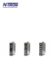
Industrial Gigabit Ethernet Switch Installation Guide 1002MC-SX 1002MC-LX-YY 1003GX2-SX 1003GX2-LX-YY 1003GX2-B 1005TX Where "YY" is: 1000BaseSX multimode fiber media converter 1000BaseLX singlemode fiber media converter 1000BaseSX multimode fiber switch 1000BaseLX singlemode fiber switch Custom mix and match 1003GX2 switch 5 port gigabit Ethernet switch 10 for 10km max. fiber segment length 40 for 40km max. fiber segment length 70 for 70km max.
Copyright, © N-TRON Corp., 2008 820 S. University Blvd., Suite 4E Mobile, AL USA 36609 All rights reserved. Reproduction, adaptation, or translation without prior written permission from N-TRON Corp. is prohibited, except as allowed under copyright laws. Ethernet is a registered trademark of Xerox Corporation. All other product names, company names, logos or other designations mentioned herein are trademarks of their respective owners.
ELECTRICAL SAFETY WARNINGS This equipment is suitable for use in Class I, Division 2, Groups A, B, C, and D or non-hazardous locations only. WARNING – Explosion Hazard – Substitution of components may impair suitability for Class I, Division 2. WARNING – Explosion Hazard – Do not disconnect while circuit is live unless area is known to be nonhazardous. WARNING – Explosion Hazard – Do not replace the device unless power has been switched off or the area is known to be non-hazardous.
ENVIRONMENTAL SAFETY WARNINGS WARNING: Disconnect the power and allow to cool 5 minutes before touching. 1000 Series Industrial Gigabit Ethernet Switches The 1000 Series Unmanaged Industrial Gigabit Ethernet Switches support high speed layer 2 switching between ports. This series of switches are housed in a ruggedized aluminum enclosure, and provide Category-5 compliant 10/100/1000Base-T connections for high performance network design, and hub/repeater upgrades.
PACKAGE CONTENTS Please make sure the package contains the following items: 1. 2. 1000 Series Media Converter or Ethernet Switch Product CD Contact your carrier if any items are damaged. UNPACKING Remove all the equipment from the packaging, and store the packaging in a safe place. File any damage claims with the carrier. CLEANING Clean only with a damp cloth.
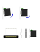
DIN-Rail Mounting Install the unit in a standard DIN rail. Recess the unit to allow at least 2” of horizontal clearance for CAT5e cable bend radius or 5” of horizontal clearance for Fiber Optic cable bend radius. To install the unit to 35mm industrial DIN rail, place the top edge of the included mounting bracket on the back of the unit against the DIN rail at a 15° angle as shown. Rotate the bottom of the unit to the back (away from you) until it snaps into place.
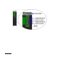
FRONT PANEL From Top to Bottom: LNK/ACT SPD1000 Green LED lights when Power is connected Link/Activity LED 1000 Speed LED LEDs: The table below describes the operating modes: LED LNK/ACT SPD1000 (Revised 8/5/2009) Color Description ON Power is Applied. OFF Power is OFF. ON Link established, no Activity on cable. BLINKING Link established, Activity on cable OFF No link activity on cable. ON Link is 1000Mbps. OFF Link is 10/100Mbs.
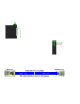
APPLYING POWER (Top View) Unscrew & Remove the DC Voltage Input Plug from the top header. Install the DC Power Cables into the Plug (observing polarity on unit). Plug the Voltage Input Plug back into the top header. Tightening torque for the terminal block power plug is 0.5 Nm/0.368 Pound Foot. All LEDs will flash ON Momentarily. Verify the Power LED stays ON (GREEN). Note: Either V1 or V2 can be connected to power for minimal operation.
N-TRON SWITCH GROUNDING TECHNIQUES FOR 1000 SERIES The grounding philosophy of any control system is an integral part of the design. N-Tron switches are designed to be grounded, but the user has been given the flexibility to float the switch when required. The best noise immunity and emissions (i.e. CE) are obtained when the N-Tron switch chassis is connected to earth ground via a drain wire. Some N-Tron switches have metal din-rail brackets that can ground the switch if the din-rail is grounded.
CONNECTING THE UNIT For 10Base-T ports, plug a Category 3 (or greater) twisted pair cable into the RJ45 connector. For 100/1000Base-T ports, plug a Category 5e (or greater) twisted pair cable into the RJ45 connector. Connect the other end to the far end station. Verify that the LNK LEDs are ON once the connection has been completed. To connect any other port to another Switch or Repeater, use a standard Cat5e straight through or crossover cable.
FCC STATEMENT This product complies with Part 15 of the FCC-A Rules. Operation is subject to the following conditions: (1) This device may not cause harmful Interference (2) This device must accept any interference received, including interference that may cause undesired operation. NOTE: This equipment has been tested and found to comply with the limits for a Class A digital device, pursuant to Part 15 of the FCC Rules.
1002MC - KEY SPECIFICATIONS Physical Height: Width: Depth w/ typical SFP installed: Weight: DIN Rail: 4.0” (10.16 cm) 1.0” (2.54 cm) 3.61” (9.165 cm) 0.70 lbs (0.32 kg) 35 mm Electrical Input Voltage: Input Current: Inrush Current: Input Ripple: Input Wire Size: 10-30 VDC (Regulated) 200mA max. @ 24VDC (Steady State) 13 Amp/0.8 ms max.
Regulatory Approvals: Safety: UL Listed per ANSI/ISA-12.12.01-2000 (US and Canada) and listed for use in Class I, Div 2, Groups A, B, C, D, T4. EMI: EN61000-6-4, EN55011 - Class A FCC Title 47, Part 15, Subpart B - Class A ICES-003 – Class A EMS: EN61000-6-2 EN61000-4-2 (ESD) EN61000-4-3 (RS) EN61000-4-4 (EFT) EN61000-4-5 (Surge) EN61000-4-6 (Conducted Disturbances) Warranty: 3 year from the date of purchase.
1003GX2 - KEY SPECIFICATIONS Physical Height: Width: Depth w/ typical SFP installed: Weight: DIN Rail: 4.0” (10.16 cm) 1.0” (2.54 cm) 3.61” (9.165 cm) 0.7 lbs (0.32 kg) 35 mm Electrical Input Voltage: Input Current: Inrush Current: Input Ripple: Input Wire Size: 10-30 VDC (Regulated) 200mA max. @ 24VDC (Steady State) 13 Amp/0.8 ms max.
Regulatory Approvals: Safety: UL Listed per ANSI/ISA-12.12.01-2000 (US and Canada) and listed for use in Class I, Div 2, Groups A, B, C, D, T4. EMI: EN61000-6-4, EN55011 - Class A FCC Title 47, Part 15, Subpart B - Class A ICES-003 – Class A EMS: EN61000-6-2 EN61000-4-2 (ESD) EN61000-4-3 (RS) EN61000-4-4 (EFT) EN61000-4-5 (Surge) EN61000-4-6 (Conducted Disturbances) Warranty: 3 year from the date of purchase.
1005TX - KEY SPECIFICATIONS Physical Height: Width: Depth: Weight: DIN Rail: 4.0” (10.16 cm) 1.0” (2.54 cm) 3.61” (9.165 cm) 0.70 lbs (0.32 kg) 35 mm Electrical Input Voltage: Input Current: Inrush Current: Input Ripple: Input Wire Size: 10-30 VDC (Regulated) 230mA max. @ 24VDC (Steady State) 13 Amp/0.61 ms max.
Regulatory Approvals: Safety: UL Listed per ANSI/ISA-12.12.01-2000 (US and Canada) and listed for use in Class I, Div 2, Groups A, B, C, D, T4. EMI: EN61000-6-4, EN55011 - Class A FCC Title 47, Part 15, Subpart B - Class A ICES-003 – Class A EMS: EN61000-6-2 EN61000-4-2 (ESD) EN61000-4-3 (RS) EN61000-4-4 (EFT) EN61000-4-5 (Surge) EN61000-4-6 (Conducted Disturbances) Warranty: 3 year from the date of purchase.
N-TRON Limited Warranty N-TRON, Corp. warrants to the end user that this hardware product will be free from defects in workmanship and materials, under normal use and service, for the applicable warranty period from the date of purchase from N-TRON or its authorized reseller.