
User Manual


(Revised 8/5/2009)
10
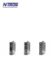
N-TRON SWITCH GROUNDING TECHNIQUES FOR 1000 SERIES
The grounding philosophy of an y control system is an integral part of the design. N-Tron swit ches are des i gned
to be grounded, but the user has been given the flexibility to float the switch when required. The best noise
immunity and emissions (i.e. CE) are obtained when t he N-Tron switch chassis is connected to earth ground via
a drain wire. Some N-Tron switches have metal din-rail brackets that can ground the switch if the din-rail is
grounded. In some cases, N-Tron switches with metal brackets can be supplied with optional pl astic bracket s if
isolation is required.
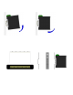
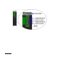
Users ma y run a drain w ire & lu g from t he scr ew provi ded on the back face o f the
enclosure. In the event the provided grounding screw has been lost, care should
be taken to limit the penetration of the outer skin by less than 1/4". Failure to do
so may cause irreversible damage to the internal components of the switch.
Note: Ensur e the power supply is grounded properly before applying power to the
grounded switch. This may be verified by using a voltmeter to determine that there
is no voltage difference between the power supply’s negative output terminal and
the chassis grounding point of the switch.
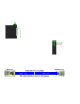
As an alternative grounding method, both V- legs of the power input
connector are connected to chassis internally on the PCB. Connecting
a drain wire to earth ground from one of the V- terminal plugs as
shown here will ground the switch and the chassis. The power leads
from the power source should be limited to 3 meters or less in length.
Note: Before applying power to the grounded switch, you must use a volt meter to verify there is no voltage
difference between the power supply’s negative output terminal and the switch chassis grounding point.
If the use of shielded cables is required, it is generally recommended to only connect the shield at one end to
prevent ground loops and interfere with low level signals (i.e. thermocouples, RTD, etc.). Cat5e cables
manufactured to EIA-568A or 568B specifications are required for use with N-Tron Switches.
In the event all Cat5e patch cable distances are small (i.e. All Ethernet devices are located the same local
cabinet and/or referenced to the same earth ground), it is permissible to use fully shielded cables terminated to
chassis ground at both ends in systems void of low level analog signals.
DRAIN WIRE WITH LUG CONNECTING SWITCH
CHASSIS TO KNOWN GOOD GROUNDING POINT .
DRAIN WIRE WITH
LUG CONNECTING
SWITCH CHASSIS
TO KNOWN GOOD
GROUNDING
POINT.
METALLIC
DIN-RAI L C LI P