
Switch User Manual

232SS21600Manual 3
B&B Electronics Mfg Co Inc – 707 Dayton Rd - PO Box 1040 - Ottawa IL 61350 - Ph 815-433-5100 - Fax 815-433-5104
Chapter 2: SETUP
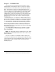
The 232SS2 is set up using an eight-position dipswitch. This
dipswitch is used to set the communication format, port
configuration, smart switch/port combiner mode and to
enable/disable the enhanced features. To change the settings on
the switch, remove the power from the unit, and remove the screws
(2) from the bottom of the 232SS2. The dipswitch is located on the
top of the PC board (side with LEDs) and is labeled “SW1.” The
other dipswitch, labeled “SW2” is used to set the second character
of the preamble. After the switches have been set to match your
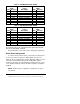
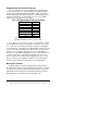
requirements, you can put the unit back together. Table 1 shows the
settings for dipswitch “SW1”.
* = FACTORY DEFAULT
Table 1. Communication & Port Setup
Dipswitch SW1
1 2 3 4 5 6 7 8 Setting
000XXXXX1200 Baud
100XXXXX2400 Baud
010XXXXX4800 Baud
110XXXXX9600 Baud *
001XXXXX19.2K Baud
101XXXXX38.4K Baud
011XXXXX57.6K Baud
111XXXXX115.2K Baud
XXX0XXXXEnhanced Disabled *
XXX1XXXXEnhanced Enable
XXXX0XXX8 Data Bits *
XXXX1XXX7 Data Bits
XXXXX0XXParity Disabled *
XXXXX1XXParity Enabled
XXXXXX0XSmart Switch Mode*
XXXXXX1XPort Combiner Mode
XXXXXXX0DCE master port *
XXXXXXX1DTE master port
0 = OFF 1 = ON X = DON'T CARE