
Switch User Manual

232SS21600 Manual
B&B Electronics Mfg Co Inc – 707 Dayton Rd - PO Box 1040 - Ottawa IL 61350 - Ph 815-433-5100 - Fax 815-433-5104
4
Port Configuration
In order to determine the proper port configuration of the
232SS2, it is necessary to have a basic understanding of the terms
DCE and DTE. RS-232 was designed, using DB-25 connectors, for
connecting a DTE (
D
ata
T
erminal
E
quipment) device to a DCE
(
D
ata
C
ommunication
E
quipment) device. Each device will have
inputs on pins that correspond to outputs on the same pins of the
other device. For example, a DTE device will transmit data out on
pin 2 (on a DB-25) and a DCE device will receive data in on pin 2
(on a DB-25). IBM PCs and serial printers are DTE devices,
modems are DCE devices.
If an IBM PC (DTE device) is going to be connected to the
232SS2 master port, the master port should be configured as a DCE
port. If a modem (DCE device) is going to be connected to the
master port, it should be configured as a DTE port.
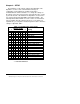
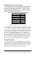
The master port can be configured as a DCE port (data received
on pin 2) or a DTE port (data received on pin 3) by setting dipswitch
“SW1”, position 8. To configure the master port as a DCE port, move
dipswitch “SW1”, position 8, to the "OFF" position. When the master
port is configured as a DCE port, ports A, B, C, & D will become
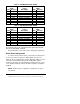
DTE ports (Refer to Table 2). To configure the master port as a DTE
port move dipswitch “SW1”, position 8, to the "ON" position. When
the master port is configured as a DTE port, ports A, B, C, & D will
become DCE ports (Refer to Table 3).
Always
power down the
smart switch when changing switch settings.