
Switch User Manual

232SS21600Manual 5
B&B Electronics Mfg Co Inc – 707 Dayton Rd - PO Box 1040 - Ottawa IL 61350 - Ph 815-433-5100 - Fax 815-433-5104
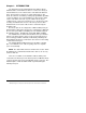
The 232SS2 supports the following RS-232 signals: TD, RD, SG,
RTS, CTS, DSR, DCD, and DTR.
The Smart Switch selects port A as the default port at power up.
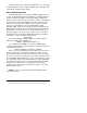
Serial Data Configuration
In order for the host device that is connected to the master port
to select any of the four ports, the Smart Switch must be set to
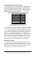
match the host's communication format. Dipswitch “SW1” is used to
select the communication format of the Smart Switch. Switch
positions 1 through 3 select the baud rate. Switch position 5 selects
7 or 8 data bits. Switch position 6 determines if parity is enabled or
disabled.
NOTE:
A data format of 7 data bits, no parity and one stop is
not allowed.
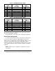
Table 2. DCE MASTER PORT CHART
Master Port
(DCE) Signal
A,B,C & D Ports
(DTE)
Pin# Direction Description Pin# Direction
2 Input Transmit Data (TD) 2 Output
3 Output Receive Data (RD) 3 Input
4 Input Request to Send (RTS) 4 Output
5 Output Clear to Send (CTS) 5 Input
6 Input DCE Ready (DSR) 6 Output
7 GROUND Signal Ground (SG) 7 GROUND
8 Output Recv. Line Detect (DCD) 8 Input
20 Input DTE Ready (DTR) 20 Output
Table 3. DTE MASTER PORT CHART
Master Port
(DTE) Signal
A,B,C & D Ports
(DCE)
Pin# Direction Description Pin# Direction
2 Output Transmit Data (TD) 2 Input
3 Input Receive Data (RD) 3 Output
4 Output Request to Send (RTS) 4 Input
5 Input Clear to Send (CTS) 5 Output
6 Output DCE Ready (DSR) 6 Input
7 GROUND Signal Ground (SG) 7 GROUND
8 Input Recv. Line Detect (DCD) 8 Output
20 Output DTE Ready (DTR) 20 Input