Model: HVD100A3 HDV100A3 Command Response Protocol Documentation Number: HDV100A3-4407CR International Headquarters B&B Electronics Mfg. Co. Inc. 707 Dayton Road -- P.O. Box 1040 -- Ottawa, IL 61350 USA Phone (815) 433-5100 -- General Fax (815) 433-5105 Home Page: www.bb-elec.com Sales e-mail: orders@bb-elec.com -- Fax (815) 433-5109 Technical Support e-mail: support@bb-elec.
Table of Contents INTRODUCTION........................................................................................ 1 Intelligent Mode Command Protocol..................................................... 2 Formatting the Control Bytes ................................................................ 3 DETAILED DESCRIPTION OF GENERAL FUNCTION CODES...... 4 Command Acknowledgement ................................................................. 4 RS-232 Baud Rate Setup ....................................
WARNING! This Model HDV100A3 Converter Module allows you to connect to active J1708 / J1939 networks. It is possible that your transmissions through this converter module could cause malfunction of the network operation, damage to software or equipment, or bodily harm. Do Not Transmit Any Messages to the network without a complete understanding of the operation of the network. B&B Electronics Mfg. Co.
Introduction The HDV100A3 adapter has two modes of operation: J1708 Intelligent and J1939 Intelligent mode In Intelligent mode the HDV100A3 works with a command protocol to control different operations of the HDV100A3. The HDV100A3 performs several functions in the intelligent mode in order to reduce the overhead and timing requirements of the host application when communicating with the J1708 bus. The device handles collision detection and retries with no additional interaction from the host application.
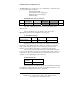
Intelligent Mode Command Protocol The HDV100A3 uses a simple protocol to communicate to vehicle bus. The protocol is divided into four parts: Start Of Frame (SOF) Control Field (shown in light gray) Data Field (shown in dark gray) Checksum (CS) SOF 1 byte Intelligent Mode Message Structure Number of Control Bytes Number of Control Bytes Data Bytes 1 byte 1 to 20 bytes 1 byte Data Bytes CS 1 to 100 bytes 1 byte The Start of Frame byte is the first byte in a valid frame and is always 01 hex.
Formatting the Control Bytes The 2nd byte is “Number of Control Bytes” to follow and always precedes the control field. The third byte is the ID byte. This byte tells the hardware where to direct the message. Valid entries for functions are: ID Codes =01 Message for J1708 =02 Message for J1939 =08 General message (for control of the HDV100A3 device) =05 Device identification (reverse compatible) The fourth byte is the function byte. The functions that are supported are listed below.
Detailed Description of General Function Codes Command Acknowledgement All commands sent to the device will be acknowledged. If no error occurs an ACK will be sent with the ID byte that accompanied the command. If an error occurred, a NACK will be sent with the ID byte that accompanied the command as well as a Function code of $05 and the Error Code. The responses will not be shown for each command since it is the same for almost all commands. Below is the format of the ACK/NACK response.
RS-232 Baud Rate Setup To set the baud rate for the RS-232 port, set a general command code of 08. Set the function code to 01. Then set 3 control bytes as follows.
Bits 1 and 0 set the word length Bit 0 0 0 1 1 Bit 1 0 1 0 1 Word Length 5 6 7 8 (default) Default value. The HDV100A3 should always be set to 8-bit word length. 6 HDV100A3 Command & Response Manual-1306cr B&B Electronics -- 707 Dayton Rd.
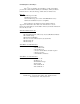
Setting Baud 1, Baud 2 Baud Rate Setup Table Baud Rate 9600 14400 19200 38,400 57,600 115,200 230,400 460,800 Decimal Divisor 48 32 24 12 8 4 2 1 Hex Divisor MSB (Baud 2) $00 (default) $00 $00 $00 $00 $00 $00 $00 Hex Divisor LSB (Baud 1) $30 (default) $20 $18 $0C $08 $04 $02 $01 All baud rates are entered as hex numbers. To calculate your own decimal divisor use the following formula. The decimal number must be converted to hexadecimal before entering the number.
Baud Rate Example To set the PC baud rate to 57,600 baud, N,8,1, format the message as follows. Byte Number 1 2 3 4 5 6 7 8 9 Byte Value Hex 01 05 08 01 03 08 00 00 1A Byte Function Start of frame Number of control bytes Command byte (08 = internal command) Function Bbte (01 = change baud) UB3 Baud 1 Baud 2 Number of data bytes Checksum The first byte is the start of frame and always 01. Next is the number of control bytes (05). There are 5 bytes in the control section (in gray).
Time Stamp Information The HDV100A3 supports a four-byte rolling time stamp with a resolution of 1.5 microseconds per bit. The maximum time stamp value is 6,442.45 seconds before roll over. The 4-byte time stamp will be added to all transmission from the bus. The time stamp will be added to the transmission confirmation message. The host application can request that the HDV100A3 send a time stamp, formatted as follows.
Byte Number 1 2 3 4 5 6 Byte Value 01 02 08 20 00 2B Function Start of frame Number of control bytes ID byte 08 = internal command Function code 20 = stop time stamping Number data bytes Checksum To resume time stamping send the following command: Byte Number 1 2 3 4 5 6 Byte Value 01 02 08 10 00 1B Function Start of frame Number of control bytes ID byte 08 = internal command Function code 10 = resume time stamping Number data bytes Checksum Time stamping will resume after reset.
Master Reset Command The master reset command allows the HDV100A3 to be reset from the PC. Sending this command resets the HDV100A3 to the default start-up state. You will lose all setting sent in the smart mode. Byte Number 1 2 3 4 5 6 7 8 Byte Value 01 04 08 08 01 02 00 18 Function Start of frame Number of control bytes ID byte 08 = internal command Function code 08= master reset Check byte Check byte Number data bytes Checksum Note: after sending a master reset the baud rate is 115,2k (default).
J1708 Commands Receiving Data from the J1708 Bus After the HDV100A3 is set into its Intelligent mode of operation and the RS-232 data rate is configured, you are now ready to communicate with the J1708 bus. A receive command must be sent to the HDV100A3 before attempting to transmit to the bus. The receive message synchronizes the HDV100A3 with the bus. To start receiving J1708 bus data, send the following to the HDV100A3.
Byte number 1 2 3 4 5 6 Byte value (hex) 01 02 01 10 00 14 Byte Function Start of frame The number of control bytes ID byte 01= J1708 Function code 10 hex stop receive Number of data bytes (00 place holder) Checksum (bytes 1 through 5 added together) After sending this command to the device, the device will respond with a confirmation message and data will cease. Note that there is the possibility of an incomplete message being sent to the PC after sending this command.
Transmitting Data to the J1708 Bus The HDV100A3 supports standard J1708 commands of up to 21 bytes. Additionally the HDV100A3 can send messages up to 100 bytes to the J1708 bus. It is the responsibility of the sending software to check for “ignition off” before using the J1708 bus to send messages with more than 21 bytes to the bus. Failure to check for a “quiet bus” condition before transmitting a long message may cause erratic bus operation.
After sending a transmit message to the HDV100A3 you will get the confirmation message if the checksum is correct. A transmit complete message is sent to the PC after the device successfully transmits the message to the J1708 bus. A second message should not be sent to the device before confirming that the first message has been sent.
J1708 Message Filter The J1708 message filter will operate on 4 different MID’s. Only messages with the same MID as set in the filter will be sent to the PC. The filters will be OR’ed together so that multiple MID’s can be filtered, MID1 or MID2 or MID3.
Broadcast Message The HDV100A3 supports one broadcast message. Once configured by the host application, this message will be sent repeatedly by the HDV100A3 at a programmed time interval. This feature is useful to provide a “heartbeat” function to the J1708 bus with no overhead to the host application’s software. Sending 0 in the time value stops the broadcast message from being sent.
To stop broadcast transmission it is not necessary to send the whole message. The message below will stop broadcast transmission. Byte Number Byte Value Function 1 2 3 4 7 8 01 02 01 07 00 0B Start of frame Control bytes ID byte 1 = J1708 message Set broadcast 7 = On X = Time interval (see chart) Data bytes Checksum Byte 4 Values Byte Value 07 17 27 37 47 Time Value Stop broadcast .5 sec. 1.0 sec 1.5 sec 2.
J1939 Commands The J1939 protocol is similar to the J1708 protocol. The message starts with Start of Frame byte 01. The number of control bytes will be 06. The control code for J1939 is 02.
wise to set the receiver off when not in use. Sending the Start Receive clears the mask. This renders the filter function useless.
Data messages received from the HDV100A3 operating in the J1939 mode, is formatted as follows: Control Field Data Field Start # of Contr Time Stamp # of Arbitration Field of Control Byte 4 Bytes Data Frame bytes Bytes 01 05 02 msb # of Data Bytes in Message lsb ZZ Y1 Y2 Y3 Y4 0X Check sum Bus Data Up to 8 Bytes The message starts with 01. The number of control bytes is 05. Next is the control byte 02, followed by the time stamp, four bytes, with msb first.
A message received from the HDV will be formatted as follows: <01><05><02><06><0D><67><80><20><00><08><7D><00>< 00> The < > are placeholders and are NOT transmitted with the data. ** = value changes with message.
Transmit Data to J1939 Bus Byte Number 1 2 3 4 5 6 7 8 9 Byte Value 01 06 02 02 XX XX XX XX DD DATA CS Function Start of frame Control bytes ID byte 1 = J1708 message Function byte 02 transmit message MSB of arbitration field (J1939 priority bits) MSB-1 MSB-2 LSB of arbitration field (J1939 source address) Number of data bytes From 0 to 8 bytes Checksum Set Mask Function code 04 set mask. The mask is applied to ALL filters. The mask is 32 bits long. The last 3 bits are not used and must be set to zero.
The mask can be used to look at a group of messages: To set the mask to filter on the J1939 priority field, the mask would be loaded with: (01, 06, 02, 04, E0, 00, 00, 00, 00, ED) To set the mask to filter on the J1939 PGN field, the mask would be loaded with: (01, 06, 02, 04, 07, FF, F8, 00, 00, 0B) To set mask to filter on both the priority field and the PGN field the mask would be loaded with: (01, 06, 02, 04, B7, FF, F8, 00, 00, BB) Set Filter 1 to 4 Function codes 18 and 19, 28 and 29, 38 and 39, 48 an
2. Set the “Mask” to the desired pattern (01, 06, 02, 04, XX, XX, XX, XX, 00, CS). 3. Set a filter (1 to 4) to the match value (01, 06, 02, YY, XX, XX, XX, XX, 00, CS). Be sure that this is NOT the same as any other filter value or the HDV100A3 may become erratic. 4. Sending this value to the HDV100A3 will continuously send this match to the PC. Note that sending the “ Start Receive” or the “Stop Receive” command resets the mask rendering the filters useless.
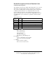
J1939 Header Worksheet This worksheet will aid in filling out/decoding the J1939 arbitration field. Bit Number 29 28 27 26 25 24 23 22 21 20 19 18 17 16 15 14 13 12 11 10 9 8 7 6 5 4 3 2 1 J1939 Function Priority Bits CAN Frame Entry Reserved Data Page PDU-Format (PGN Byte 2) 0 0 Hex Value Byte 1 Byte 2 PDU Specific (PGN Byte 3) Byte 3 Source Address Byte 4 0 0 0 26 HDV100A3 Command & Response Manual-1306cr B&B Electronics -- 707 Dayton Rd.
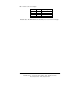
Error Codes Error Code Format: Byte Number Byte Value 1 01 2 03 3 05 4 XY 5 0Z 6 00 7 CS Error Code DEC 1 2 3 4 5 6 7 8 9 10 11 12 13 14 15 HEX 1 2 3 4 5 6 7 8 9 A B C D E F Function Start of frame Number of control bytes Function code error = 05 ID of message that caused error Error code (see chart below) Number of data bytes Checksum Type of Error Generated Meaning of Error Generated Gen Gen Gen J1708 J1708 J1708 Inbuffer overflow; more than 127 bytes Checksum mismatch Protocol error; function, ID,