
User Guide


2 HDV100A3 Command & Response Manual-1306cr
B&B Electronics -- 707 Dayton Rd. -- PO Box 1040 -- Ottawa, IL 61350
PH (815) 433-5100 -- FAX (815) 433-5104
Intelligent Mode Command Protocol
The HDV100A3 uses a simple protocol to communicate to vehicle bus. The
protocol is divided into four parts:
Start Of Frame (SOF)
Control Field (shown in light gray)
Data Field (shown in dark gray)
Checksum (CS)
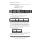
Intelligent Mode Message Structure
SOF
Number of
Control Bytes
Control Bytes Number of
Data Bytes
Data Bytes CS
1 byte 1 byte 1 to 20 bytes 1 byte 1 to 100 bytes 1 byte
The Start of Frame byte is the first byte in a valid frame and is
always 01 hex.
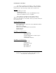
The Control Field sets up the function and control of the
HDV100A3 hardware and is formatted as shown below.
Control Field Structure
Number of Control
Bytes to Follow
ID Byte Function
Byte
Control Data Bytes
1 byte 1 byte 1 byte Up to 20 bytes
The first byte of the Control Field is the number of control bytes in
the message. This value indicates the number of control bytes, excluding
itself, to follow. If the message doesn’t contain any control bytes, the
Number of Control Bytes value will be set to 00 hex as a placeholder.
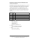
The next part of the message frame is the data field. The data field
is preceded by the number of data bytes, excluding itself, to follow and is set
to 00 hex if no data is present in the message. The data field is reserved for
data that is to be communicated to the vehicle bus.
Data Field Structure
Number of
Data Bytes
Data Bytes
1 byte Up to 100 bytes
The last element of a valid message is the checksum. The checksum
is calculated by adding ALL bytes from the Start of Frame (inclusive) to the
last data byte and using the last 8 bits as a checksum.