Models: ESP901, ESP901E, ESP902, ESP902E Multi-Interface Ethernet Serial Servers (RS-232/422/485) Manual Documentation Number: ESP901-902-3704m B&B Electronics Mfg Co Inc – 707 Dayton Rd - PO Box 1040 - Ottawa IL 61350 - Ph 815-433-5100 - Fax 815-433-5104 – www.bb-elec.com B&B Electronics Ltd – Westlink Commercial Pk – Oranmore, Galway, Ireland – Ph +353 91-792444 – Fax +353 91-792445 – www.bb-europe.
International Headquarters B&B Electronics Mfg. Co. Inc. 707 Dayton Road Ottawa, IL 61350 USA Phone (815) 433-5100 -- General Fax (815) 433-5105 Website: www.bb-elec.com Sales e-mail: orders@bb-elec.com -- Fax (815) 433-5109 Technical Support e-mail: support@bb.elec.com -- Fax (815) 433-5104 European Headquarters B&B Electronics Ltd. Westlink Commercial Park Oranmore, Co. Galway, Ireland Phone +353 91-792444 -- Fax +353 91-792445 Website: www.bb-europe.com Sales e-mail: sales@bb-europe.
2004 B&B Electronics. No part of this publication may be reproduced or transmitted in any form or by any means, electronic or mechanical, including photography, recording, or any information storage and retrieval system without written consent. Information in this manual is subject to change without notice, and does not represent a commitment on the part of B&B Electronics.
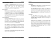
CHAPTER 4: USING ESP MANAGER........................................................ 21 HARDWARE SETUP ......................................................................................... 21 SOFTWARE SETUP ........................................................................................... 22 SOFTWARE OVERVIEW ................................................................................... 23 Menus................................................................................................
CHAPTER 7: REMOVING VIRTUAL COM PORTS................................ 49 REMOVING THE VIRTUAL COM PORT WITH ESP MANAGER .......................... 49 REMOVING THE VIRTUAL COM PORT USING DEVICE MANAGER ................... 50 CHAPTER 8: UPGRADING THE SERIAL SERVER FIRMWARE........ 53 DOWNLOADING THE FIRMWARE ..................................................................... 53 UPGRADING VIA ESP MANAGER .................................................................... 53 Preparing the Software ..........
Introduction Chapter 1: INTRODUCTION Introduction Features • Multi-interface serial ports o ESP901 and ESP902 Port 1 software selectable for RS232, RS-422, RS-485 (DIP Switch selects Console Mode) o ESP902 Port 2 is RS-232 only • 10/100 Mbps Ethernet with Auto Selection • LAN and WAN Communications • TCP or UDP Client or Server operation - configurable • Software Support - Windows 98/ME/2000/XP or NT 4.
Introduction Introduction Communication Modes The ESP901 and ESP902 Serial Servers enable communication with serial devices over a LAN or WAN. Serial devices no longer are limited to a physical connection to the PC COM port. They can be installed anywhere on the LAN using TCP/IP or UDP/IP communications. This allows traditional Windows PC software access to serial devices anywhere on the LAN/WAN network. Paired Mode Paired Mode is also called serial tunneling.
Introduction Introduction Software Installation Serial Server Quick Start Guide For descriptive purposes this Quick Start Guide considers a typical configuration consisting of a PC connected via an Ethernet LAN to an ESP901 or ESP902 Serial Server connected to the RS-232 port of a serial device. Using the CD included with the Serial Server, install the VLINX ESP Manager software on the configuring computer. Serial Server Configuration Step 1: Open the ESP Manager software.
Introduction Introduction Step 5: Re-enter Server Properties to verify the changes have taken effect, or to view/change the configuration of other ports. Each port must be configured separately. Install Virtual COM Ports on PC Step 1: From the Windows Start menu, run the Install Virtual COM Ports utility included with the VLINX software, Step 2: Search for all servers on the network Step 3: Select a port and map it to an unused COM port (e.g. Port 15).
Making Hardware Connections Chapter 2: MAKING THE HARDWARE CONNECTIONS Making Hardware Connections Indicator Lights Package Checklist Light Indication Power Red - power is applied Link Yellow – 10BaseT Ethernet connection established Green – 100BaseTX Ethernet connection established Ready Flashing Green – system is ready ESP901 and ESP902 Serial Servers are shipped with the following Figure 5.
Making Hardware Connections DIP Switches A triple DIP (dual inline package) switch allows the Serial Server to be placed into Console Mode. When all three switches are moved into the ON position the Serial Server enters Console Mode, allowing configuration of the Serial Server (using an RS-232 connection through the serial port on the ESP901 or Serial Port 1 on the ESP902) from a PC running a terminal program such as HyperTerminal.
Making Hardware Connections Default Mode Making Hardware Connections RS-422 Mode In RS-422 Mode the currently selected serial port is configured as an RS-422 interface supporting four RS-422 signal channels with full duplex operation for Receive, Transmit, RTS (Request To Send) and CTS (Clear To Send). The data lines are differential pairs (A & B) in which the B line is positive relative to the A line in the idle (mark) state. Ground provides a common mode reference.
Making Hardware Connections Making Hardware Connections Serial Server Serial Port Connector Pin-outs Pin-outs for RS-232, RS-422 and RS-485 operation are shown below.
Installing the VLINX ESP Software Installing the VLINX ESP Software Chapter 3: INSTALLING THE VLINX ESP SOFTWARE Figure 13. The Windows-based ESP Manager and Virtual COM Port software makes configuration fast and easy. If using Windows, installing the ESP Manager software and setting up virtual COM ports to configure the Serial Server is recommended. The Install Shield Wizard Window Step 2: When the VLINX ESP Setup window appears, click Next.
Installing the VLINX ESP Software Installing the VLINX ESP Software The recommended procedure is to Remove all installed components first. Once the software has been removed, Install the new software. Opening the ESP Manager Step 5: If the Serial Server is not already connected to the network or to the Ethernet port on the computer, connect it. Set all the DIP switches to the OFF position. Apply power.
Using ESP Manager Using ESP Manager Chapter 4: USING ESP MANAGER The ESP Manager software allows: • Searching for servers connected to the network • Displaying and changing the configuration of those servers • Installing virtual COM ports on a computer • Displaying and configuring virtual COM ports • Uninstalling virtual COM ports on a computer • Upgrading the Serial Server firmware • Monitoring Port Status • Saving and Loading Configuration Files Hardware Setup Figure 20.
Using ESP Manager Using ESP Manager • Searching Server - Searches for Serial Servers on the network and brings back configuration information that will be displayed in the Server Properties window. Figure 21. • Uninstall Virtual COM - Allows virtual COM ports to be uninstalled from the ESP Manager window.
Using ESP Manager Exit Help • Using ESP Manager • Allows you to Exit the ESP Manager program • Port - Displays the port number for each Serial Server port. Flow Control - Indicates what type of flow control is configured for each port. • • Accesses the About vcomui dialogue box, which indicates the software version number Status - Indicates whether each port is currently In Use or Not Used.
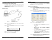
Using ESP Manager Using ESP Manager Step 5: Enter the IP Address assigned to the desired Serial Server or click Search all reachable servers, then OK. IP Address is used to find Serial Server units that are not on the same subnet. (Routers on the network will block the standard broadcast used to find servers if Search all reachable servers is selected.) The user must set an IP address that conforms to the LAN addressing scheme.
Using ESP Manager Figure 26. Using ESP Manager The Restarting Dialogue Box After eight seconds a dialogue box will ask whether you want to search for all reachable servers again. Figure 27. The Server Search Dialogue Box While the Serial Server is searching for all reachable servers the following dialogue box appears: Figure 28.
Server Properties Configuration Server Properties Configuration Description of the Server Properties Chapter 5: CONFIGURING THE SERIAL SERVER PROPERTIES The VLINX Serial Server can be configured using any of four different user interfaces: the ESP Manager software, Console Mode, Telnet or the Web Server. The Server Properties described in this chapter can be changed from any of these user interfaces. Figure 30.
Server Properties Configuration address, net mask, and gateway to the Serial Server. If a DHCP server is not available on the network the Serial Server will time out after 10 seconds and the default values will remain. When DHCP is enabled, the IP Address, Netmask and Gateway fields become inaccessible and cannot be changed by the user. Server Properties Configuration Netmask The default LAN netmask is configured for a Class C address. The user may change this. Default is 255.255.255.
Server Properties Configuration Server Properties Configuration communications are ideal for 5 seconds the Serial Server will reset and make itself available for another client connection. Flow Control The Flow Control setting must match the requirements of the serial device connected. TCP Alive Timeout The Serial Server monitors TCP activity. If TCP activity stops for the length of time specified in this field the connection will be closed. This field can be set to any value between 0 and 255 minutes.
Server Properties Configuration Server Properties Configuration • Port Status This field indicates whether a serial port is connected via the Serial Server to a virtual COM port of a device on the network. Connection At TCP/UDP Port When the Connection Mode field is set to Client or Client (no heartbeat), this field becomes active, allowing the ESP901/902 (acting as a client) to connect to the server either on Power up or on Data Arrival (first character arriving).
Server Properties Configuration Server Properties Configuration After that port has been updated you may want to re-enter Server Properties to verify the changes have taken effect, or to view/change the configuration separately. of other ports. Each port must be configured Saving Configuration Data in Console Mode or Telnet Figure 33. Saving (updating) server properties is done from the Configuration screen.
Server Properties Configuration Server Properties Configuration Web Server Interface • The Web Server interface provides the same updating options as Console Mode and Telnet. These are located at the bottom of all three Web Server pages. If a field is changed, you must click Save before leaving that page or the changes will be ignored. Figure 37. The Web Server Page Note: If you leave any Web Server page without saving, any changes you have made will be ignored.
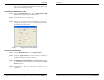
Installing Virtual COM Port Installing Virtual COM Port The program searches the LAN for all available Serial Servers. When complete, the Found Server window appears and displays a list of the servers that were found. Chapter 6: INSTALLING VIRTUAL COM PORTS The Virtual COM Port feature allows Windows platform software, using standard API calls, to be used in an Ethernet application. The Install Virtual COM Port software adds a Serial Server (COM#) port to the computer.
Installing Virtual COM Port Installing Virtual COM Port Matching the Serial Server and Virtual COM Port Settings The settings of the virtual COM ports in the Device Manager and the Serial Server Configuration Menu must match. If the settings do not match, the virtual COM ports will not work. If these settings are changed in the Device Manager, it will only affect the operation of the virtual COM port. It will not change the settings stored in the Serial Server.
Installing Virtual COM Port Installing Virtual COM Port . Figure 43. The VLINX ESP (COM3) Properties Window Step 4: Click the Configuration or Port Settings tab. This screen allows the settings to be changed if necessary. Click Cancel to keep the existing settings. Step 5: Click OK to change the settings. Use Refresh in the Device Manager if Windows does not auto refresh.
Removing Virtual COM Ports Removing Virtual COM Ports Chapter 7: REMOVING VIRTUAL COM PORTS Step 3: Click the Uninstall Virtual COM icon. The Manager will ask for conformation. Click OK to complete the uninstall procedure. The ESP Manager software Uninstall Virtual COM Port feature will remove a mapped COM port in the Device Manager of Windows 2000 and XP operating systems. It may also be removed in the Device Manager of Windows 98, ME, NT, 2000, and XP.
Removing Virtual COM Ports Figure 46. Removing Virtual COM Ports The Control Panel Window Figure 48. Step 3: Click Device Manager in the Systems Properties window. In the Device Manager dialogue click the + next to Ports (COM LPT) to expand. Figure 47. Confirm Device Removal Step 5: click OK to proceed.
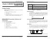
Upgrade Mode Upgrade Mode Step 4: Click Yes on the vcomui dialogue to restart the Serial Server. Chapter 8: UPGRADING THE SERIAL SERVER FIRMWARE Upgrading the Firmware Step 5: Double-click the Firmware Upgrade icon (or click the Server menu and Firmware Upgrade) Step 6: In the Upgrade window, click Browse. The Open dialogue box will appear. Locate the folder on your PC that contains the firmware .hex file. Select the file and click Open. The Open dialogue box will disappear.
Using Console Mode Using Console Mode Navigating the Configuration Menus Chapter 9: USING CONSOLE MODE There are six Console Mode screens: Server, Network, Serial Mode, Operation, Monitor and Configuration. Tab, Back Space and arrow keys can be used to highlight the desired function on the screen list. Pressing Enter moves the cursor to the first field with the current screen. The configuration fields can be changed by pressing Enter and selecting from the list that appears.
Using Console Mode Using Console Mode Step 5: Once all the changes have been made move to the Configuration screen, select Save and press Enter. Figure 51. Saving and Restarting the Configuration The restart message will appear. Step 6: Select Yes to save changes. This is necessary to write the settings to the server. Using a Password If a password is used it must be entered before the Configuration screen can be seen.
Using the Web Server Using the Web Server Navigate and change properties as required using the mouse and keyboard. Chapter 10: USING THE WEB SERVER To change serial port properties, click Serial Port on the left side of the browser window. The following page will appear: The Web Server can be used to configure the Serial Server from any web browser software (such as Internet Explorer). Server properties can be set up using three browser pages. Note: See Chapter 5 for details on Server Properties.
Using the Web Server Figure 54. Using the Web Server The Web Server Operation Page Click Save to store changes to the Serial Server. Settings for each Port must be saved separately. Note: If new property settings are not saved before leaving this page they will not take effect. Return to the main Server page by clicking on Server on the left side of the browser window.
Using Telnet Using Telnet Step 6. The Telnet window will open (unless the server is still in Console mode) and the Server screen will appear. CHAPTER 11: Using Telnet Telnet can be used to configure the Serial Server from any PC on the LAN. The Telnet window displays the same configuration information shown in Console Mode and allows server properties to be configured. Navigating the Configuration Menu There are six Telnet screens: Server, Network, Serial Mode, Operation, Monitor and Configuration.
Using Telnet Using Telnet Step 7: Once all the changes have been made move to the Save field and select Enter. The restart message will appear. Figure 57. Saving and Restarting the Configuration Step 8: Select Yes to save changes. This is necessary to write the settings to the server. The Telnet window will disappear. Step 9: To view the changes re-enter Telnet and re-establish communications. The configuration menu will appear and display the current settings. Figure 56.
ESP901 and ESP902 Technical Data Chapter 12: ESP901 and ESP902 TECHNICAL DATA Hardware and Included Accessories ESP901 and ESP902 Serial Server modules Power Supply: 12 VDC/500mA (tip positive/sleeve negative) Power Plug: (Area Dependent: North America 120VAC/60Hz, Europe/United Kingdom 220/240VAC/50Hz) Manual: Paper copy of this manual, PDF available CD-ROM disc: VLINX ESP Manager and Virtual COM Driver software for Windows 98/ME/2000/XP/NT 4.0 Dimensions ESP901/ESP902: 3.35 x 4.5 x 0.90 in (8.5 x 11.
ESP901 and ESP902 Technical Data Default Server Settings Server Name Serial Number: unit) Password: DHCP: IP Address: Net Mask: Gateway: MAC Address: Version&Date: date Serial server port: Baud Rate: Data//Stop: Parity: Flow Control: TCP/UDP Protocol: Serial timeout: TCP alive timeout: Connection Mode: Delimiter HEX 1: Delimiter HEX 2: Force transmit: TCP/UDP port: Serial port mode: Max connection: Remote IP Address: Manual Documentation Number: ESP901-902-3704 ESP901 and ESP902 Technical Data ESP901
RS-232 Connections RS-232 Connections RS-232 Straight-through Cable Connections APPENDIX A: RS-232 CONNECTIONS In the RS-232 mode, the Serial Server’s ports are configured as DTEs like a computer.
RS-232 Connections RS-232 Straight-through DB-9 to DB-25 Conversion Connections RS-232 Connections RS-232 DTE Loopback Connections Figure 65. Figure 63. For Transmit and Receive loopback, connect only those lines. DB-9 to DB-25 Straight-through Cable Connections RS-232 Crossover DB-9 to DB-25 Conversion Connections Figure 64. Loopback Connections for RS-232 When Flow Control setting on the Serial Server is set for RTS/CTS, those lines must be looped. Usually DTR and DSR must also be looped.
RS-422 Connections RS-422 Connections Serial Server pin-out in RS-422 mode APPENDIX B: RS-422 CONNECTIONS RS-422 Device RS-422 Signal Names Serial Server DB-9 Pin-outs in RS-422 Mode RS-422 Signal Name Direction RS-422 DB9M Pin Receive Data A (−) In RXDA (−) 1 Receive Data B (+) In RXDB (+) 2 Transmit Data B (+) Out TXDB (+) 3 Transmit Data A (−) Out TXDA (−) 4 Signal Ground --- GND 5 Clear to Send A (−) In CTSA (−) 6 Clear to Send B (+) In CTSB (+) 7 Request to Send B
RS-422 Connections Figure 68. RS-422 Connections Loopback Connections for RS-422 The RS-485 Connections are half duplex, either Receive or Transmit, so another half duplex device must be used to check operation. Figure 69. RS-422 Connection with No Flow Control Manual Documentation Number: ESP901-902-3704 Appendix B 77 B&B Electronics Mfg Co Inc – 707 Dayton Rd - PO Box 1040 - Ottawa IL 61350 - Ph 815-433-5100 - Fax 815-433-5104 – www.bb-elec.
RS-485 Connections RS-485 Connections APPENDIX C: RS-485 CONNECTIONS Serial Server DB-9 Pin-out in RS-485 Mode RS-485 Signal Name Direction RS-485 DB9M Pin Data B (+) In/Out DATA B (+) 3 Data A (−) In/Out DATA A (−) 4 Signal Ground --- GND 5 Figure 70.
Network Connections APPENDIX D: NETWORK CONNECTIONS Network Connections Crossover Ethernet Cable RJ-45 Pin-out Standard Ethernet Cable RJ-45 Pin-out RJ-45 Pin Signal Wire Color RJ-45 Pin 1 TX+ White-Green 1 2 TX+ Green 2 3 RX+ White-Orange 3 4 Not used Blue 4 5 Not used White-Blue 5 6 RX- Orange 6 7 Not used White-Brown 7 8 Not used Brown 8 Figure 72.
International Headquarters B&B Electronics Mfg. Co. Inc. 707 Dayton Road Ottawa, IL 61350 USA Phone (815) 433-5100 -- General Fax (815) 433-5105 Website: www.bb-elec.com Sales e-mail: orders@bb-elec.com -- Fax (815) 433-5109 Technical Support e-mail: support@bb.elec.com -- Fax (815) 433-5104 European Headquarters B&B Electronics Ltd. Westlink Commercial Park Oranmore, Co. Galway, Ireland Phone +353 91-792444 -- Fax +353 91-792445 Website: www.bb-europe.com Sales e-mail: sales@bb-europe.