Washer-Extractor A-computer Programming and Operating Instructions cY01 B&C Technologies Accurate Technologies Panama City, FL (850) 249-2222 (850) 249-2226 FAX www.bandctech.com Samutprakarn, Thailand +66 (0) 2740-5511 +66 (0) 2740-5522 FAX www.accuratethai.com Revision 1.
Table of Contents Introduction Customer Service Replacement Parts 3 3 Safety Information Key Symbols Important Safety Information 4 5 Operation Cycle Selection Cycle Execution Check Cycle 6 6 8 Programming Key Functions Setup Mode Cycle Count Cycle Programming Cycle Segment Tables Programming Worksheets Factory Programs B&C Technologies Accurate Technologies Panama City, FL (850) 249-2222 (850) 249-2226 FAX www.bandctech.com Samutprakarn, Thailand +66 (0) 2740-5511 +66 (0) 2740-5522 FAX www.
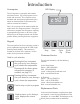
Introduction A-computer LED Display The A-computer is a powerful and versatile solid state control. Up to 30 programs can be stored and executed. The computer comes standard with several pre-programmed cycles, which are discussed later in the manual (see table of contents for locations). cY01 Note: Do not power off the machine while the mode switch is in Program position. Doing this will result in program data corruption, requiring a reprogramming of some or all of the cycles.
Key Symbols Anyone operation or servicing this machine must follow the safety rules in this manual.
Important Safety Information SAFETY CHECK LIST Before machine is placed in operation, the door safety interlock must be checked for proper operation as follows: Before Initial start up of a washer – extractor perform the following safety check: A. A. B. C. D. Make sure all electrical and plumbing connections have been made in accordance with applicable codes and regulations. Make sure the machine is grounded electrically.
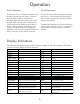
Operation Cycle Selection Cycle Execution Press the up or down key until the desired cycle number is showing on the display. Press the keys just hard enough to activate them. Pressing harder will cause undue wear on the keypad. After you arrive at the desired cycle, ensure the goods are loaded, and the door is closed. Then press Start. If the door is not properly closed and locked, the display will read Door until the door is properly closed and locked. After the door is closed, press start.
Operation Cycle Execution (continued) Gentle Wash Cycles 8, 16, and 24 use a gentle agitation profile. This profile is used in the prewash, wash, and rinse steps. The gentle wash agitation profile is: Each of the 30 cycles consists of 8 segments. A typical cycle has Prewash, Wash, and Rinses (up to six are available). Upon the completion of the last rinse, a final spin occurs. Following is a description of each cycle segment.
Operation 1. Machine rotates wash forward and displays "F". This motion continues until the operator presses advance (up+down). Cycle Execution (continued) Stop Routine When the final spin of the wash cycle is complete, the stop routine is activated. The stop routine sequence looks like this: > > > > > > > 3. Machine rotates wash reverse and displays "r". This motion continues until the operator presses advance (up+down).
Operation 10. The A-computer energizes supply 4 and displays "S4". Hold this state until operator presses advance (up+down). 11. The A-computer energizes the heat output and displays "ht". Hold this state until operator presses advance (up+down). 12. The A-computer energizes the fwd output and opens the drain until all three water levels turn off. The display shows “drin”. Hold this state for 5 additional seconds 13.
Programming Key Functions in Program Mode The computer board is located inside the control module. In the middle of the board is a small toggle switch used to change from Run mode to Program mode (see illustration). The Up key is used to increase cycle numbers and other numerical values, like time and temperature, when creating wash formulae. The Down key is used to decrease cycle numbers and other numerical values, like time and temperature, when creating wash formulae.
Programming Setup Mode The setup options are programmable options that are in operation during all wash cycles. The options are: > > > > Temperature displayed in degrees Celsius or Fahrenheit. Spray Rinse and Supply 4 enabled Auxiliary heat and Spray Rinse enabled Auxiliary heat and Supply 4 enabled To enable Auxiliary Heat and Supply 4, press the Up or Down key to see HEAT. Press the start key (enter). Now press the Up or Down key to see SUP4.
Programming Cycle Programming (continued) When modifying a cycle time, a time must be entered for each segment. To skip a segment or spin, enter 00 for the time and press the Start key. The following table shows the range of time allowed for each segment and spins, as well as the allowed temperature range for machines equipped with auxiliary heat.
Programming After you have set the spin time, press the Start key, The display will now show the name of the next program segment. See the chart on page 10 for the list of program segments and what the display indicates for each. Cycle Programming (continued) After selecting your desired supply option, press the Start key. If your machine is equipped with Auxiliary heating, and it was enabled during Setup programming, you may use the up or down key to select the target temperature for the segment.
Programming Cycle Segment Charts (continued) Wash Segment Details Use Up or Down to change. Start key is enter or advance Display UASH 00 or 02 - 30 Segment time: 00 to skip, or any time between 0 and 30 minutes HFIL CFIL BFIL Fill temperature: Hot, Cold, or Warm (both fill) LOLE, nDle or HILE Select Fill level, Low, Med or High SUP0 - SUP7 Select Supply 0-7 (0 for no supply during the step) 00, 75 - 200 Enter temperature: 75-200 deg F, 25-93 deg C. 00 for no heat.
Programming Cycle Segment Charts (continued) Fill 6 Segment Display Details Use Up or Down to change. Start key is enter or advance fil6 00 or 02 - 30 Segment time: 00 to skip, or any time between 0 and 30 min HFIL CFIL BFIL Fill temperature: Hot, Cold, or Warm (both fill) LOLE ndle or HILE Select Fill level, Low Med or High SUP0 - SUP7 Select Supply 0-7 (0 for no supply during the step) 00, 75 - 200 Enter temperature: 75-200 deg F, 25-93 deg C. 00 for no heat.
Programming Blank Cycle Chart Program Number Segment Detail Segment Detail Fill 3 Prewash Prewasy/Flush Time (min) Water Temp Water Level Supply Temp Spin (sec) Wash Time (min) Water Temp Water Level Supply Temp Spin (sec) Spray/Dilution Time (min) Water Temp Water Level Supply Temp Spin (sec) Fill 4 Spray/Dilution Time (min) Water Temp Water Level Supply Temp Spin (sec) Fill 1 Fill 5 Spray/Dilution Time (min) Water Temp Water Level Supply Temp Spin (sec) Spray/Dilution Time (min) Water Temp Water
Factory Programs Cold Wash Normal Program Number: 1 S egment D e t ail P rew as h Prewasy/Flush Time (min) Water Temp Water Level Supply Temp Spin (sec) Was h Time (min) Water Temp Water Level Supply Temp Spin (sec) S egment F il l 3 Spray/Dilution Time (min) Water Temp Water Level Supply Temp Spin (sec) 05 cfil hile sup1 00f 0 Spray/Dilution Time (min) Water Temp Water Level Supply Temp Spin (sec) 08 cfil ndle sup2 00f 60 00 F il l 5 Spray/Dilution Time (min) Water Temp Water Level Supply Temp Sp
Factory Programs W arm W ash Normal Program Number: 2 S egment D e t ail P rew as h Prewasy/Flush Time (min) Water Temp Water Level Supply Temp Spin (sec) Was h Time (min) Water Temp Water Level Supply Temp Spin (sec) S egment F il l 3 Spray/Dilution Time (min) Water Temp Water Level Supply Temp Spin (sec) 05 bfil hile sup1 00f 0 Spray/Dilution Time (min) Water Temp Water Level Supply Temp Spin (sec) 08 bfil ndle sup02 00f 60 00 F il l 5 Spray/Dilution Time (min) Water Temp Water Level Supply Temp
Factory Programs Hot Wash Normal Program Number: 3 S egment D e t ail P rew as h Prewasy/Flush Time (min) Water Temp Water Level Supply Temp Spin (sec) Was h Time (min) Water Temp Water Level Supply Temp Spin (sec) S egment Fil l 3 Spray/Dilution Time (min) Water Temp Water Level Supply Temp Spin (sec) 05 hfil hile sup1 00f 0 Spray/Dilution Time (min) Water Temp Water Level Supply Temp Spin (sec) 08 hfil ndle sup2 00f 60 00 Fil l 5 Spray/Dilution Time (min) Water Temp Water Level Supply Temp Spin
Factory Programs Rinse & Spin Program Number: 6 S egment D e t ail P rew as h Prewasy/Flush Time (min) Water Temp Water Level Supply Temp Spin (sec) Was h Time (min) Water Temp Water Level Supply Temp Spin (sec) S egment F il l 3 Spray/Dilution Time (min) Water Temp Water Level Supply Temp Spin (sec) 00 Spray/Dilution Time (min) Water Temp Water Level Supply Temp Spin (sec) 00 00 F il l 5 Spray/Dilution Time (min) Water Temp Water Level Supply Temp Spin (sec) 00 F il l 2 Spray/Dilution Time (min
Factory Programs Reclaim Program Number: 7 S egment D e t ail P rew as h Prewasy/Flush Time (min) Water Temp Water Level Supply Temp Spin (sec) Was h Time (min) Water Temp Water Level Supply Temp Spin (sec) S egment F il l 3 Spray/Dilution Time (min) Water Temp Water Level Supply Temp Spin (sec) 20 hfil ndle sup4 00f 60 Spray/Dilution Time (min) Water Temp Water Level Supply Temp Spin (sec) 02 hfil ndle sup0 00f 60 02 bfil hile sup0 00f 60 F il l 5 Spray/Dilution Time (min) Water Temp Water Level
Factory Programs Turnout Gear - Firehouse Duty Machines Only Program Number 8 Segment D et ail P rewas h Prewasy/Flush Time (min) Water Temp Water Level Supply Temp Spin (sec) Was h Time (min) Water Temp Water Level Supply Temp Spin (sec) Segment Fill 3 Spray/Dilution Time (min) Water Temp Water Level Supply Temp Spin (sec) prew 00 Spray/Dilution Time (min) Water Temp Water Level Supply Temp Spin (sec) 08 cfill mdle sup1 00f 00 00 Fill 5 Spray/Dilution Time (min) Water Temp Water Level Supply Temp