
Instruction Manual

PULL INVert:
When pushed in, the polarity of the channel 2 signal
is normal. When pulled out, the polarity of the
channel 2 signal is reversed, thus inverting the
waveform.
19. CH2 VOLTS/DIV Control. Vertical attenuator for
channel 2. Provides step adjustment of vertical sensi-
tivity. When channel 2 VARiable control is set to
CAL, vertical sensitivity is calibrated in 10 steps from
5 mV/div to 5 V/div in a 1-2-5 sequence. When the
X-Y mode of operation is selected, this control pro-
vides step adjustment of Y-axis sensitivity.
20. CH2 VARiable/PULL X5 MAG Control:
VARiable:
Rotation provides vernier adjustment of channel 2
vertical sensitivity. In the fully-clockwise (CAL)
position, the vertical attenuator is calibrated. Coun-
terclockwise rotation decreases gain sensitivity. In
X-Y operation, this control becomes the vernier
Y-axis sensitivity control.
PULL X5 MAG:
When pulled out, increases vertical sensitivity by a
factor of five. Effectively provides two extra sensi-
tivity settings: 2 mV/div and 1 mV/div. In X-Y
mode, increases Y-sensitivity by a factor of five.
21. CH2 (Y) Input Jack. Vertical input for channel 2.
Y-axis input for X-Y operation.
22. CH2 AC-GND-DC Switch. Three-position lever
switch with the following positions:
AC:
Channel 2 input signal is capacitively coupled; dc
component is blocked.
GND:
Opens signal path and grounds input to vertical
amplifier. This provides a zero-volt base line, the
position of which can be used as a reference when
performing dc measurements.
DC:
Direct coupling of channel 2 input signal; both ac
and dc components of signal produce vertical de-
flection.
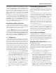
HORIZONTAL CONTROLS
23. Main Time Base TIME/DIV Control. Provides step
selection of sweep rate for the main time base. When
the VARiable Sweep control is set to CAL, sweep rate
is calibrated. This control has 23 steps, from 0.1 µS/div
to 2 S/div, in a 1-2-5 sequence.
24. 2125C & 2160C. DELAY Time Base TIME/DIV
Control. Provides step selection of sweep rate for
delayed sweep time base. This control has 23 steps,
from 0.1 µS/div to 2 S/div, in a 1-2-5 sequence.
25. 2125C & 2160C. DELAY TIME POSition Control.
Sets starting point of delayed sweep. Clockwise
rotation causes delayed sweep to begin earlier.
26. VARiable Sweep Control. Rotation
of control is ver-
nier adjustment for sweep rate. In fully
clockwise
(CAL) positi
on, sweep rate is calibrated. On the
Model 2125C, this control is the vernier adjustment
for both the main and delayed time bases.
27. POSition/PULL X10 MAG Control.
POSition:
Horizontal (X) position control.
PULL X10 MAG:
Selects ten times sweep magnification when pulled
out, normal when pushed in. Increases maximum
sweep rate to 10 nS/div.
28. 2125C & 2160C. Sweep Mode Switch. Selects
sweep (horizontal) mode. Four-position rotary switch
with the following positions:
MAIN:
Only the main sweep operates,
with the delayed
sweep inactive.
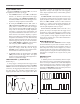
MIX:
The main and delayed sweep share
a single trace;
main sweep occupies the left portion of the display;
delayed sweep occupies the right portion of the
display. The DELAY TIME POSition control de-
termines the percentage of display that is main
sweep and the percentage of display that is delayed
sweep (main sweep is usually brighter than the
delayed sweep). Delayed sweep speed cannot be
slower than main sweep speed.
DELAY:
Only delayed sweep operates, while main sweep
stays inactive. DELAY TIME POSition control
determines the starting point of the delayed sweep.
X-Y:
Used with the VERTical MODE switch and Trig-
ger SOURCE switch to select X-Y operating
mode. The channel 1 input becomes the X-axis and
the channel 2 input becomes the Y-axis. Trigger
source and coupling are disabled in this mode.
29. 2120C Only. X-Y Switch. Used with the VERTical
MODE switch and Trigger SOURCE switch to se-
lect X-Y operating mode. The
channel 1 input be-
comes
the X-axis and the channel 2 input becomes the
Y-axis. Trigger source and coupling are disabled in
this mode.
CONTROLS AND INDICATORS
9