
Instruction Manual

TRIGGERING CONTROLS
30. HOLDOFF/PULL CHOP Control.
HOLDOFF:
Rotation adjusts holdoff time (trigger inhibit period
beyond sweep duration). When control is rotated
fully counterclockwise, the holdoff period is MIN-
inum (normal). The holdoff period increases pro-
gressively with clockwise rotation.
PULL CHOP:
When this switch is pulled out in the dual-trace
mode, the channel 1 and channel 2 sweeps are
chopped and displayed simultaneously (normally
used at slower sweep speeds). When it is pushed in,
the two sweeps are alternately displayed, one after
the other (normally used at higher sweep speeds).
31. Trigger SOURCE Switch. Selects source of sweep
trigger. Four-position lever switch with the following
positions:
CH1/X-Y/ALT
CH1:
Causes the channel 1 input signal to become the
sweep trigger, regardless of the VERTical
MODE switch setting.
X-Y:
Used with two other switches to enable the X-Y
mode — see the Operating Instructions under
“XY Operation”.
ALT:
Used with the channel 1 POSition/PULL
ALTernate TRIGger control to enable alternate
triggering. Alternate triggering, used in dual-
trace mode, permits each waveform viewed to
become its own trigger source.
CH2:
The channel 2 signal becomes the sweep trigger,
regardless of the VERTical MODE switch setting.
LINE:
Signal derived from input line voltage (50/60 Hz)
becomes trigger.
EXT:
Signal from EXTernal TRIGger jack becomes
sweep trigger.
32. Trigger COUPLING Switch. Selects trigger cou-
pling. Four-position lever switch with the following
positions:
AUTO:
Selects automatic triggering mode. In this mode, the
oscilloscope generates sweep (free runs) in absence
of an adequate trigger; it automatically reverts to
triggered sweep operation when an adequate trigger
signal is present. On the Model 2125C & 2160C
automatic triggering is applicable to both the main
sweep and delayed sweep.
NORM:
Selects normal triggered
sweep operation. A sweep
is generated only when an adequate trigger
signal is
present.
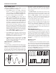
TV-V:
Used for triggering from television vertical sync
pulses. Also serves as lo-pass/dc (high frequency
reject) trigger coupling.
TV-H:
Used for triggering from television horizontal sync
pulses. Also serves as hi-pass (low frequency reject)
trigger coupling.
33. TRIGger LEVEL/PULL (-) SLOPE Control.
TRIGger LEVEL:
Trigger level adjustment; determines the point on
the triggering waveform where the sweep is trig-
gered. Rotation in the (-) direction (counterclock-
wise) selects more negative triggering point;
rotation in the (+) direction (clockwise) selects
more positive triggering point.
PULL (—) SLOPE:
Two-position push-pull switch. The “in” position
selects a positive-going slope and the “out” position
selects a negative-going slope as triggering point for
main sweep.
34. EXTernal TRIGger Jack. External trigger input for
single- and dual-trace operation.
REAR PANEL CONTROLS (not shown)
35. Fuse Holder/Line Voltage Selector. Contains fuse
and selects line voltage.
36. Power Cord Receptacle.
37. 2125&& CH 2 (Y) SIGNAL OUTPUT Jack.
Output terminal where sample of channel
2 signal is
available. Amplitude of
output is nominally 50 mV per
division of vertical deflection seen on CRT when
terminated into 50 Ω. Output impedance is 50 Ω.
38. 2125&& Z-Axis Input Jack. Input jack for inten-
sity modulation of CRT electron beam.
TTL compat-
ible (5 V p-p sensitivity). Positive levels increase
intensity.
39.
Handle/Tilt Stand.
40. Feet/Cord Wrap.
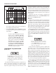
CONTROLS AND INDICATORS
10