
Instruction Manual

OPERATING TIPS
The following recommendations will help obtain the best
performance from the oscilloscope.
1. Always use the probe ground clips for best results,
attached to a circuit ground point near the point of
measurement. Do not rely solely on an external ground
wire in lieu of the probe ground clips as undesired
signals may be introduced.
2. Avoid the following operating conditions:
a. Direct sunlight.
b. High temperature and humidity.
c. Mechanical vibration.
d. Electrical noise and strong magnetic fields, such as
near large motors, power supplies, transformers,
etc.
3. Occasionally check trace rotation, probe compensa-
tion, and calibration accuracy of the oscilloscope using
the procedures found in the MAINTENANCE section
of this manual.
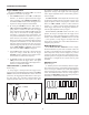
4. Terminate the output of a signal generator into its
characteristic impedance to minimize ringing, espe-
cially if the signal has fast edges such as square waves
or pulses. For example, the typical 50 Ω output of a
square wave generator should be terminated into an
external 50 Ω terminating load and connected to the
oscilloscope with 50 Ω coaxial cable.
5. Probe compensation adjustment matches the probe to
the input of the scope. For best results, compensation
should be adjusted initially, then the same probe al-
ways used with the same channel. Probe compensation
should be readjusted when a probe from a different
oscilloscope is used.
INITIAL STARTING PROCEDURE
Until you familiarize yourself with the use of all controls,
the settings given here can be used as a reference point to
obtain a trace on the CRT in preparation for waveform
observation.
1. Set these controls as follows:
On both models:
VERTical MODE to CH1.
CH1 AC/GND/DC to GND.
Trigger COUPLING to AUTO.
Trigger SOURCE to CH1.
All POSition controls and INTENSITY control cen-
tered (pointers facing up).
Main Time Base control to 1 mS/div.
On the Model 2125C & 2160C:
Sweep Mode switch to MAIN.
2. Press the red POWER pushbutton (Model 2120C &
2160C), or rotate the POWER control
clockwise
“away from "OFF" (Model 2125C & 2160C).
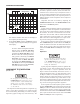
3. A trace should appear on
the CRT. Adjust the
trace
brightness with the INTENSITY control, and the
trace sharpness with the FOCUS control.
NOTE
On the Model 2125C & 2160C you can use
the BEAM FINDER pushbutton to locate a
trace that has been moved off the screen by
the POSition controls. When the button is
pushed, a compressed version of the trace
is brought into view which indicates the
location of the trace.
SINGLE TRACE DISPLAY
Either channel 1 or channel 2 may be used for single-trace
operation. To observe a waveform on channel 1:
1. Perform the steps of the “Initial Starting Procedure”.
2. Connect the probe to the CH 1 (X) input jack.
3. Connect the probe ground clip to the chassis or com-
mon of the equipment under test. Connect the probe
tip to the point of measurement.
4. Move the CH1 AC/GND/DC switch out of the GND
position to either DC or AC.
5. If no waveforms appear, increase the sensitivity by
turning the CH 1 VOLTS/DIV control clockwise to a
position that gives 2 to 6 divisions vertical deflection.
6. Position the waveform vertically as desired using the
CH1 POSition control.
7. The display on the CRT may be unsynchronized. Refer
to the “Triggering” paragraphs in this section for pro-
cedures on setting triggering and sweep time controls
to obtain a stable display showing the desired number
of waveforms.
DUAL TRACE DISPLAY
In observing simultaneous waveforms on channel 1 and
2, the waveforms are usually related in frequency, or one of
the waveforms is synchronized to the other, although the
basic frequencies are different. To observe two such related
waveforms simultaneously, perform the following:
1. Connect probes to both the CH 1 (X) and CH 2 (Y)
input jacks.
2. Connect the ground clips of the probes to the chassis
or common of the equipment under test. Connect the
tips of the probes to the two points in the circuit where
waveforms are to be measured.
OPERATING INSTRUCTIONS
12