
Instruction Manual
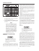

Trigger SOURCE Switch
The trigger SOURCE switch (CH 1, CH 2, etc.) selects
the signal to be used as the sync trigger.
1. If the SOURCE switch is set to CH 1 (or CH 2) the
channel 1 (or channel 2) signal becomes the trigger
source regardless of the VERTICAL MODE selec-
tion. CH 1,orCH 2 are often used as the trigger source
for phase or timing comparison measurements.
2. By setting the SOURCE switch to ALT (same as
CH1) and PULL ALT TRIG pulled, alternating trig-
gering mode is activated. In this mode, the trigger
source alternates between CH 1 and CH 2 with each
sweep. This is convenient for checking amplitudes,
waveshape, or waveform period measurements, and
even permits simultaneous observation of two wave-
forms which are not related in frequency or period.
However, this setting is not suitable for phase or timing
comparison measurements. For such measurements,
both traces must be triggered by the same sync signal.
Alternate triggering can only be used in dual-trace
mode (VERT MODE set to DUAL), and with alter-
nate sweep only (PULL CHOP not engaged).
3. In the LINE position, triggering is derived from the
input line voltage (50/60 Hz) and the trigger
SOURCE switch is disabled. This is useful for meas-
urements that are related to line frequency.
4. In the EXT position, the signal applied to the EXT
TRIG jack becomes the trigger source. This signal
must have a timing relationship to the displayed wave-
forms for a synchronized display.
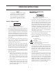
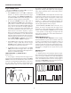
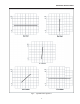
TRIG LEVEL/PULL (–) SLOPE Control
(Refer to Fig. 3)
A sweep trigger is developed when the trigger source
signal crosses a preset threshold level. Rotation of the TRIG
LEVEL control varies the threshold level. In the + direction
(clockwise), the triggering threshold shifts to a more posi-
tive value, and in the − direction (counterclockwise), the
triggering threshold shifts to a more negative value. When
the control is centered, the threshold level is set at the
approximate average of the signal used as the triggering
source. Proper adjustment of this control usually synchro-
nizes the display.
The TRIG LEVEL control adjusts the start of the sweep
to almost any desired point on a waveform. On sine wave
signals, the phase at which sweep begins is variable. Note
that if the TRIG LEVEL control is rotated toward its
extreme + or − setting, no sweep will be developed in the
normal trigger mode because the triggering threshold ex-
ceeds the peak amplitude of the sync signal.
When the PULL (–) SLOPE control is set to the + (“in”)
position, the sweep is developed from the trigger source
waveform as it crosses a threshold level in a positive-going
direction. When the PULL (–) SLOPE control is set to the
− (“out”) position, a sweep trigger is developed from the
trigger source waveform as it crosses the threshold level in
a negative-going direction.
MAIN TIME BASE Control
Set the Main Time Base TIME/DIV control to display
the desired number of cycles of the waveform. If there are
too many cycles displayed for good resolution, switch to a
faster sweep time. If only a line is displayed, try a slower
sweep time. When the sweep time is faster than the wave-
form being observed, only part of it will be displayed, which
may appear as a straight line for a square wave or pulse
waveform.
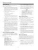
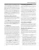
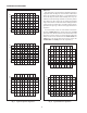
HOLDOFF Control
(Refer to Fig. 4)
A “holdoff” period occurs immediately after the comple-
tion of each sweep, and is a period during which triggering
of the next sweep is inhibited. The normal holdoff period
varies with sweep rate, but is adequate to assure complete
retrace and stabilization before the next sweep trigger is
permitted. The HOLDOFF control allows this period to be
extended by a variable amount if desired.
Slope “–” Range
Slope “+” Range
Level
+
–
Fig. 3. Function of Slope and Level Controls.
OPERATING INSTRUCTIONS
A. Holdoff not used
B. Holdoff used
Fig. 4. Use of HOLDOFF Control.
14