
Instruction Manual

This control is usually set to the MIN position (fully
counterclockwise) because no additional holdoff period is
necessary. The HOLDOFF control is useful when a com-
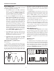
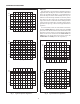
plex series of pulses appear periodically such as in Fig. 4B.
Improper sync may produce a double image as in Fig. 4A.
Such a display could be synchronized with the VA R
SWEEP control, but this is impractical because time meas-
urements are then uncalibrated. An alternate method of
synchronizing the display is with the HOLDOFF control.
The sweep speed remains the same, but the triggering of the
next sweep is “held off” for the duration selected by the
HOLDOFF control. Turn the HOLDOFF control clock-
wise from the MIN position until the sweep starts at the
same point of the waveform each time.
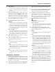
MAGNIFIED SWEEP OPERATION
Since merely shortening the sweep time to magnify a
portion of an observed waveform can result in the desired
portion disappearing off the screen, magnified display
should be performed using magnified sweep.
Using the POSition control, move the desired portion
of waveform to the center of the CRT. Pull out the PULL X10
knob to magnify the display ten times. For this type of display
the sweep time is the Main Time Base TIME/DIV control
setting divided by 10. Rotation of the POSition control can
then be used to select the desired portion of the waveforms.
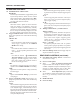
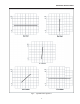
X−Y OPERATION
X−Y operation permits the oscilloscope to perform many
measurements not possible with conventional sweep opera-
tion. The CRT display becomes an electronic graph of two
instantaneous voltages. The display may be a direct com-
parison of the two voltages such as stereoscope display of
stereo signal outputs. However, the X−Y mode can be used
to graph almost any dynamic characteristic if a transducer is
used to change the characteristic (frequency, temperature,
velocity, etc.) into a voltage. One common application is fre-
quency response measurements, where the Y axis corresponds to
signal amplitude and the X axis corresponds to frequency.
1. On Models 2125C & 2160C, set the SWEEP MODE
switch to the X−Y position. On the Model 2120C, de-
-press the X−Y switch. On both models, set the Trigger
Source and VERTical MODE switches to X−Y.
2. In this mode, channel 1 becomes the X axis input and
channel 2 becomes the Y axis input. The X and Y
positions are now adjusted using the POSition and
the channel 2 POSition controls respectively.
3. Adjust the amount of vertical (Y axis) deflection with
the CH 2 VOLTS/DIV and VARIABLE controls.
4. Adjust the amount of horizontal (X axis) deflection
with the CH 1 VOLTS/DIV and VARIABLE con-
trols.
VIDEO SIGNAL OBSERVATION
Setting the COUPLING switch to the TV-H or TV-V
position permits selection of horizontal or vertical sync
pulses for sweep triggering when viewing composite video
waveforms.
When the TV-H mode is selected, horizontal sync pulses
are selected as triggers to permit viewing of horizontal lines
of video. A sweep time of about 10 µs/div is appropriate for
displaying lines of video. The VAR SWEEP control can be
set to display the exact number of waveforms desired.
When the TV-V mode is selected, vertical sync pulses are
selected as triggers to permit viewing of vertical fields and
frames of video. A sweep time of 2 ms/div is appropriate for
viewing fields of video and 5 ms/div for complete frames
(two interlaced fields) of video.
At most points of measurement, a composite video signal
is of the (−) polarity, that is, the sync pulses are negative and
the video is positive. In this case, use (− ) SLOPE. If the
waveform is taken at a circuit point where the video wave-
form is inverted, the sync pulses are positive and the video
is negative. In this case, use (+) SLOPE.
APPLICATIONS GUIDEBOOK
B+K Precision offers a “Guidebook to Oscilloscopes”
which describes numerous applications for this instrument
and important considerations about probes. It includes a
glossary of oscilloscope terminology and an understanding
of how oscilloscopes operate. It may be downloaded free of
charge from our Web site, www.bkprecision.com.
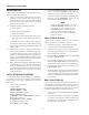
DELAYED SWEEP OPERATION (Models 2125C
& 2160C) (Refer to Fig. 5)
Delayed sweep operation is achieved by use of both the
main sweep and the delayed sweep and allows any portion
of a waveform to be magnified for observation. Unlike X10
magnification, delayed sweep allows selectable steps of
magnification.
1. Set the Sweep Mode switch to the MAIN position and
adjust the oscilloscope for a normal display.
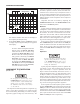
2. Set the Sweep Mode switch to the MIX position. The
display will show the main sweep on the left portion
(representing the MAIN Time Base control setting)
and the delayed sweep on the right portion (repre-
senting the DELAY Time Base control setting). The
MAIN Time Base portion of the trace usually will be
brighter than the delayed time base portion. Fig. 5
shows a typical display for the MIX display mode.
3. Shift the percentage of the display that is occupied by
the main sweep by adjusting the DELAY TIME
POSition control. Counterclockwise rotation causes
more of the display to be occupied by the main sweep
OPERATING INSTRUCTIONS
15