
Instruction Manual
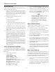

and clockwise rotation causes more of the display to
be occupied by the delayed sweep.
4. Set the Sweep Mode switch to the DELAY position
to display only the magnified delayed sweep portion
of the display.
NOTE
In order to obtain meaningful results with
delayed sweep, the DELAY Time Base
control must set be set to a faster sweep
speed than the MAIN Time Base control.
Because of this, the oscilloscope automat-
ically prevents (electrically) the DELAY
Time Base from being set to a slower
sweep speed than the MAIN Time Base.
For example, if the MAIN Time Base is set
to 0.1 ms/div, the slowest possible DELAY
Time Base sweep speed is also 0.1 ms/div,
even if the control is set slower.
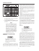
COMPONENT TEST OPERATION
(Model 2125&&)
Do not apply an external voltage to the
COMP TEST jacks. Only non-powered
circuits should be tested with this unit.
Testing powered circuits could damage
the instrument and increase the risk of
electrical shock.
The component test function produces a component “sig-
nature” on the CRT by applying an ac signal across the
device and measuring the resulting ac current. The display
represents a graph of voltage (X) versus current (Y). The
component test function can be used to view the signatures
of resistors, capacitors, inductors, diodes, and other semi-
conductor devices. Devices may be analyzed in-circuit or
out-of-circuit and combinations of two or more devices may
be displayed simultaneously. Each component produces a
different signature and the components can be analyzed as
outlined below.
Component Test mode is activated by depressing the
COMPonent TEST switch. The SWEEP MODE switch
must not be in the DELAY position.
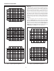
Resistors
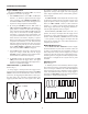
A purely resistive impedance produces a signature that is
a straight line. A short circuit produces a vertical line and an
open circuit causes a horizontal line. Therefore, the higher
the resistance, the closer to horizontal the trace will be.
Values from 10 Ω to about 5 kΩ are within measurement
range. Values below 10 Ω will appear to be a dead short
while values above 5 kΩ will appear to be an open circuit.
Fig. 6 shows some typical resistance signatures.
To test a resistor, insert one of the resistor’s leads into the
white COMP TEST jack, and the other into the GND jack
(make sure that the leads touch the metal walls inside the
jacks). To test in-circuit, a pair of test leads can be used to
connect the COMP TEST and GND jacks to the compo-
nent(s).
Capacitors
Be sure to discharge capacitors (by short-
ing the leads together) before connecting
to the COMP TEST jack. Some capaci-
tors can retain a voltage high enough to
damage the instrument.
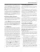
A purely capacitive impedance produces a signature that
is an ellipse or circle. Value is determined by the size and
shape of the ellipse. A very low capacitance causes the
ellipse to flatten out horizontally and become closer to a
straight horizontal line and a very high capacitance causes
the ellipse to flatten out vertically and become closer to a
straight vertical line. Values from about 0.33 µF to about
330 µF are within measurable range. Values below 0.33 µF
will be hard to distinguish from an open circuit and values
above 330 µF will be hard to distinguish from a short circuit.
Fig. 7 shows several typical capacitance signatures.
To test a capacitor, insert the capacitor’s positive lead into
the white COMP TEST jack, and the negative lead into the
GND jack (make sure that the leads touch the metal walls
inside the jacks). To test in-circuit or to test a capacitor with
leads that are too short to fit into the COMP TEST and GND
jacks, a pair of test leads can be used to connect the COMP
TEST and GND jacks to the component(s).
OPERATING INSTRUCTIONS
100
90
10
0
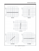
Main
Sweep
Delayed Sweep
Fig. 5. MIX SWEEP MODE Display.
16