
User Manual
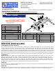

INSTALLATION INSTRUCTIONS
STEP FOUR
With the latch pin mechanism on the driver’s side, raise the center section of the hitch into position against the front cross
member from beneath the truck. The round tube hitch receiver that protrudes from the center section must t through the
hole in the truck bed oor. Fasten the center section to the front cross member using three ½” x 1 ½” bolts. Move the rear
cross member into place against the center section and fasten using three ½” x 1 ½” bolts. With the cross members, side
plates and center section installed, torque all fasteners to 90- ft. lbs. In the following sequence: First torque the side plates
to the frame. Second, torque the cross members to the side plates. Third, torque the center section to the cross members.
STEP FIVE
To install the safety chain brackets, it is necessary to drill four ½” holes through the truck bed
oor. Drill the holes from beneath the truck, through the 4 holes nearest the round hitch receiver
tube in the center section. This will locate the safety chain brackets in the valley section of the
bed oor. Drop a U-bolt through each pair of holes from the topside of the truck bed oor. Place
a spring and lock nut on each of the four legs and tighten the lock nuts until ¼” of the thread
extends through the lock nut.
STEP SEVEN
Retract the latch pin by pulling the handle out until it stops and then rotating to the lock out position. Place the 2-5/16” ball
in the hitch receiver. Engage the latch pin by rotating the handle back to center. Be certain the latch pin passes through the
holes in the 2-5/16” ball and fully engages through the hitch receiver. Repeat this process with the 2-5/16” ball in all eight
positions. Grease the base of the 2-5/16” ball.
Copyright 2014
B&W Custom Truck Beds, Inc.
ALL RIGHTS RESERVED
1000R- 05 01 2014
STEP ONE
Begin by verifying and measuring the correct hole location in the truck bed oor. Measure from the back end (tail gate end)
of the truck bed oor by hooking a tape measure over the back of the sheet metal and marking the oor at the 49 1/2”.
Center the measurement between the fender wheel wells. This location is critical to the correct installation of this hitch, so
measure, mark and saw carefully. If the truck has a plastic bed liner, you may drill through both, but it is more difcult to
accurately locate the midpoint between the fender wheel wells, and to be sure that the bed liner does not move while sawing
the hole. Make a 4-inch hole at this location using a four inch hole saw, or by marking a 4 inch circle and cutting it out with
a sabersaw equipped with a metal cutting blade.
STEP TWO
Select the front cross member. This is the longer of the two cross members. With the horizontal side up and the slotted side
facing the rear of the truck, position it across the top of the frame rails, between the bed and the frame, by pushing it through
the opening in the wheel well. Place the rear cross member behind the rst with the horizontal side up and the slotted side
facing the front of the truck. With the two cross members approximately parallel, position them about 9” apart, equally spaced
in front and behind the hole in the truck bed oor, with the ends extended 2” over the frame rails.
STEP THREE
Install the side plates by aligning two of the lower holes in the side plate with existing holes in the truck frame rails and fasten
into place using two ½”x 1 ½” bolts with a at washer on each side and a lock washer and nut on each. Hand tighten bolts.
When installing the driver’s side side plate, you may have to pull the brake line down to accommodate the bolts. Bolts should
be inserted from the inside. Fasten the front cross member to the side plates using ½” x 1 ½” bolts.
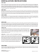
LATCH
PIN
TAB
IN−LINE
DRIVER SIDE
STEP SIX – INSTALL LATCH PIN RELEASE HANDLE
WARNING: LATCH PIN WILL NOT FUNCTION PROPERLY IF HANDLE IS NOT INSTALLED CORRECTLY.
Install the latch pin release handle by inserting it through the slot in
the end of the center section on the driver’s side of the truck. Align the
handle eyelet with the square hole in the latch pin so the handle is in
line with the latch pin as shown. Secure the handle to the pin with the
5/16 X 3/4” carriage bolt and 5/16” locking ange nut as shown. Note:
The included 5/16” cap screw can replace the carriage bolt if wrench
access on the “cab side” of the handle is limited. Tighten the nut until
it is secure. Do not over-tighten and deform the handle eyelet.