
Owner manual
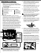
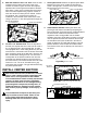
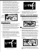
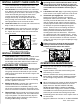

Figure A1: View of bottom of truck.
PREPARING TO INSTALL
NOTE: Remove all parts from the packaging and
familiarize yourself with all the parts and tools required.
Use the parts list on the front page to verify that all parts
and hardware are present.
TOOLS REQUIRED
Impact wrench or ratchet with 10mm, 9/16", 3/4" &
15/16" sockets.
Marking tool ( pencil or permanent marker)
3−1/2" hole saw Flashlight
Drill with 9/16" & 1/4" bits
Eye protection
Ear protection
Torque wrench
Lifting device
Center punch
Tape measure Soap and water
Pry Bar
Determine cab clearance: Under the truck bed,
measure from the rear most edge of the C−channel frame
crossmember (over the axle) to the end of the bed, see
figure A1, Length A. Next, inside the bed, measure the
length of the bed from the rear edge to the front, see
figure A1, Length B. Subtract the crossmember
measurement (length A) from the bed measurement
(Length B). Then subtract and additional 6 inches. This
will give you the amount of clearance you have between
the 2−5/16" ball location and the cab. Measure the
distance from the center of the coupler to the farthest
forward corner point of the trailer. Compare this distance
to the measurement from the center of the ball to the cab.
These measurements will allow you to see how much
clearance you will have between the cab and the trailer
while towing and turning, see figure A2.
Cab clearance on short bed trucks is very limited
when towing certain trailers. Failure to insure that
there will be adequate clearance, may result in
significant property damage, or serious injury.
Figure A2: Truck and trailer diagram
Remove the spare tire (optional). Following the
vehicle manufacturer’s instructions, remove the
spare tire. This will provide easier access to the
area where the hitch will be installed.
Remove the heatshield (optional): Remove the
bolts connecting the heatshield to the frame and
set the heatshield aside for later installation.
Position the vehicle. Installation of the hitch
requires the installer to be under the truck bed in
the area of the rear axle. Lifting the vehicle makes
this area more accessible to the installer, and
improves the installation process.
Lift vehicle using only equipment designed for
lifting and positioning vehicles for service.
Failure to do so may result in property
damage, serious injury, or death.
Prepare a lifting device (optional). The purpose
of the device is to safely hold the hitch in position
during part of the installation. See figure A3 for an
example. A simple mechanical lifting device is
available for purchase from B&W.
Remove or modify fender liners as needed.
Some vehicles are equipped with various designs
of plastic liners inside the rear wheel wells. If the
liner in the driver side wheel well prevents access
to the opening between the bed and the frame,
just over the axle, it may need to be removed or
cut to install the handle.
Disconnect the exhaust hanger: Locate the
exhaust hanger in the rear passenger portion of
the truck, see figure A4. Disconnect the exhaust
from the hanger to provide improved mounting
access to the center section. It is recommended
that a pry bar be used to aid in disconnecting the
exhaust hanger, as shown in figure A4.
1.
2.
3.
4.
5.
6.
7.
Figure A3
Figure A4: Looking under truck bed towards cab
CENTER OF 2−5/16" BALL TO CAB
COUPLER TO EDGE OF TRAILER
LENGTH A
LENGTH B
Measured on the top of the bed.
EXHAUST HANGER
EXHAUST
Length B
Length A
B − A − 6"=
Center of
ball to cab.
(write down results
for future reference
when checking
additional trailers
for clearance)
6"
PRY BAR