
Owner manual
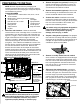

Mark the location of the 3−1/2" hole. Insert the hole
template into the center hole of the frame cross
member as shown in figure A5. Push the template
upward until it is flush against the bottom of the bed
floor. Make a mark on the truck bed floor through the
hole in the hole template using a pencil, marker, or
other tool. Once the center point is marked, remove
the template. Use a center punch to place an
indention in the truck bed at the center of the mark.
Using a drill and a ¼" bit, drill a pilot hole through the
bed in this location.
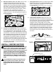
Cut the 3−1/2" diameter hole.
From the top side of
the bed, use the pilot hole and a hole saw to create a
3−1/2" diameter hole in the truck bed floor. A saber
saw equipped with a metal cutting blade may also be
used if the 3−1/2" diameter circle is laid out on the bed
floor around the center of the pilot hole. Remove any
burrs created while cutting the hole. The size of the
round portion of the hitch that will be seen from the
truck bed was determined by the size of the hole in
the truck’s frame. The closest nominal hole size to this
feature is 3−1/2". The 3−1/2" hole will leave a gap
around the hitch structure. This gap will be filled in by
the plastic spacer block.
Most trucks have fuel lines, brake lines, electrical
wires or other vehicle systems located along the
frame rails or in the general area where B&W
Turnoverball hitches install. Carefully examine the
locations of these systems before installation.
Make certain that these are not damaged during
positioning hitch components, drilling holes, or
tightening fasteners. Damage to these systems
may result in property damage, serious injury, or
death.
Turnoverball hitch components are heavy and
may be cumbersome to handle. Failure to use
proper lifting techniques and caution when
handling these items could result in serious
injury.
INSTALL CENTER SECTION
8.
1.
9.
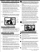
Place spacer block.
Position the plastic spacer block
between the frame cross member and the bed as
shown. See figure B1. Center the hole in the spacer
block over the hole in the frame.
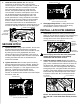
Install fastener handles.
Identify the driver and
passenger side fastener handles by comparing the
parts to figure B2. Place the fastener handles between
the frame cross member and the bed on their
respective sides, see figure B3. Use the handle
welded to the nuts to guide them into place. Once the
nuts are positioned, lower the handle so that the tab
on the bottom side of the handle fits in the hole as
shown in figure B4. This will help guide the nuts into
position while the center section is installed. Make
sure that the three nuts are directly over the holes in
the frame.
2.
Figure B3:
Looking at passenger side wheel well.
Figure B4: Cutaway view looking down into bed.
Figure A5: View under bed looking towards the cab.
Figure B1: Looking up at bed from foward of driver side tire.
Figure B2: Fastener handles.
DRIVER SIDE
PASSENGER SIDE
FASTENER
HANDLES
FASTENER HANDLE TAB
HOLE FOR TAB
HOLE TEMPLATE
FRAME CROSSMEMBER
HOLE TEMPLATE
FRAME CROSSMEMBER
TAB