
Owner manual
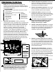

Install the center section. With the latch pin
mechanism on the drivers side, raise the center
section into place as shown, see figure B5. In order to
clear structures under the truck bed, the center will
have to be lifted into place on an angle over the
exhaust, then positioned directly under the frame
cross member so that the raised portion of the center
can be pushed straight up through the hole in the
frame cross member, and through the hole in the
plastic spacer block. Having assistance in the bed to
guide the top of the center section is recommended.
Line the 6 holes in the center section up with the
frame holes and the holes in the threaded blocks.
Thread a 5/8 flange head bolt into each hole. Next, run
the bolts in until they are about 1/16" from being tight.
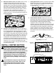
Square the hitch.
Using a tape measure, be sure that
the full length of the gooseneck hitch is centered
within the channel of the frame cross member. Do this
by making sure that the gap between the center
section and the frame cross member is the same on
the driver and passenger sides. The hitch must not be
touching the brake lines that are anchored to the
frame cross member.
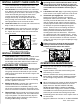
Tighten the bolts. With the hitch square and firmly
pressed against the frame cross member, tighten the
5/8" bolts. Tighten the center bolt of each three−bolt
pattern first, see figure C1. Then tighten the rest, see
figure C2. To better access the bolts on the
passenger side of the center section move the
exhaust as needed to allow access to the bolts.Torque
the bolts to 100 ft. lbs.
3.
1.
3.
1.
2.
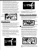
Install bolts.
Retract the latching mechanism by
pulling on the tab with the square holes and pushing it
toward the cab. From the top down, insert a 3/8
carriage bolt in each of the square holes in the
latching mechanism, see figure D1.
Serious injury can occur due to the pinch point
located at the intersection of the latching
mechanism and the center section.
Install the latch pin handle. Beginning under the
vehicle, "thread" the end of the handle, with the vinyl
grip, in front of the brake lines and over the frame on
the drivers side. Attach the handle to the latching
mechanism over the 3/8 carriage bolts with two 3/8
locking flange nuts, see figure D2. Be sure that the
handle is in the proper position and that it does not
interfere with any other components of the vehicle.
Torque the nuts to 30 ft. lbs. to secure the handle.
Notice: The latch handle must be positioned on
the "cab side" of the brake lines directly over the
axle.
SECURE HITCH
INSTALL LATCH PIN HANDLE
Disengage lifting device. If a lifting device was
used to hold the center section in place during
the installation, remove it at this time
.
2.
Figure C1: View under bed looking at center
(Exhaust pushed toward inside.)
Figure C2: View under bed looking at center.
(Exhaust pushed toward outside)
Figure D1: Looking up at center section.
Figure D2: Looking back at driver side of center section.
Figure B5: Looking from rear towards cab.
TIGHTEN FIRST
TIGHTEN SECOND
TIGHTEN SECOND
CENTER
SECTION
CARRIAGE
BOLTS
LATCHING
MECHANISM
LATCH HANDLE
3/8" CENTER
LOCK NUTS
CENTER
SECTION
LATCH PIN
MECHANISM
FRAME CROSSMEMBER