Single Zone Gas Monitors HGM-SZ (Halogen) and AGM-SZ (Ammonia) Instruction 3015-4256 Installation / Operation / Maintenance Rev 10 – April 2011 UL 61010-1 CSA 22.2 No.
Single Zone Gas Monitor Notice: Effective as of revision 4, this instruction manual refers to the current “new style” of Single-Zone leak monitoring equipment (which has its pump mounted on the inside bottom of the cabinet). For information on the older style of monitoring equipment (pump mounted to the inside top of the cabinet), refer to Rev 3 of this manual. Contact Bacharach for additional information.
Single Zone Gas Monitor WARRANTY Bacharach, Inc. warrants to Buyer that at the time of delivery this Product will be free from defects in material and manufacture and will conform substantially to Bacharach Inc.'s applicable specifications. Bacharach's liability and Buyer's remedy under this warranty are limited to the repair or replacement, at Bacharach's option, of this Product or parts thereof returned to Seller at the factory of manufacture and shown to Bacharach Inc.
Single Zone Gas Monitor iv P/N: 3015-4256 Rev 10
Single Zone Gas Monitor Table of Contents SECTION 1. INTRODUCTION..................................................................................................................... 1 1.1. 1.2. 1.3. 1.4. 1.5. 1.6. 1.7. How to Use This Manual..................................................................................................................... 1 Warning Statements ...........................................................................................................................
Single Zone Gas Monitor 3.4.2. Clearing / Silencing a Gas Alarm .......................................................................................... 21 3.4.3. Viewing the Gas Alarm Log ................................................................................................... 21 3.5. System Faults ................................................................................................................................... 22 3.5.1. Overview.................................................
Single Zone Gas Monitor SECTION 1. INTRODUCTION 1.1. How to Use This Manual Thank you for investing in a BACHARACH Single Zone Monitor. This manual provides important information on how to install, operate, and service the SZ monitoring unit. To assure operator safety and the proper use of the monitor, please read, understand, and follow the contents of this manual. If you have a working knowledge of gas monitors, you will find this manual useful as a reference tool.
Single Zone Gas Monitor 1.5.2. Protective Grounding Under no circumstances should the SZ unit be operated without connection to a protective ground. Doing so poses a potential shock hazard and is also a violation of electrical safety standards applicable to this type of equipment. 1.5.3. Explosive Atmosphere Do not operate this equipment in the presence of flammable liquids, vapors or aerosols. Operation of any electrical equipment in such an environment constitutes a safety hazard. 1.5.4.
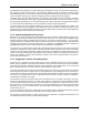
Single Zone Gas Monitor The Bacharach SZ is designed to continuously test for the presence of gas in an area that is located up to 500 ft (152.4 m) away from the monitor. The SZ monitor displays the type of gas being monitored, along with displaying both the current gas level and the peak gas level detected in that area on its front panel LCD. The monitor retains a log of previous readings that can be easily accessed for analysis.
Single Zone Gas Monitor Figure 1-1. Aerial View of Example Single Zone Leak Monitor Placement in a Mechanical Room 1.7. Specifications Category HGM-SZ Specifications Product Type Single-zone infrared monitoring system for low level continuous monitoring of CFC, HCFC and HFC refrigerant gasses used in most commercial refrigeration systems. System design supports compliance to the refrigerant monitoring requirements of ANSI/BSR ASHRAE 152007 and ASHRAE Safety Code 34-2007.
Single Zone Gas Monitor Category AGM-SZ Specifications Product Type Single zone infrared monitoring system for low level continuous monitoring of ammonia refrigerant gas used in most commercial refrigeration systems.
Single Zone Gas Monitor SECTION 2. INSTALLATION 2.1. Installation Considerations 2.1.1. Warnings and Cautions WARNING: Explosion hazard! Do not mount the SZ monitor in an area that may contain flammable liquids, vapors or aerosols. Operation of any electrical equipment in such an environment constitutes a safety hazard. WARNING: Shock hazard! Always disconnect AC power before working inside the monitor. CAUTION: Drilling holes in the SZ enclosure may damage the unit and will void the warranty.
Single Zone Gas Monitor Figure 2-1. Enclosure Mounting Specs Hold the monitor flat against the mounting surface and allow it to slide down engaging the screw heads in the keyhole slots of the mounting brackets. Adjust the screws as necessary to hold the monitor securely against the mounting surface. 2.3. Connecting Gas Sample and Exhaust Lines 2.3.1. Overview A single gas-sample line must be run from the SZ unit to the area of the facility to be monitored.
Single Zone Gas Monitor 2.3.2. Tubing Considerations Use ¼ in. outside diameter (0.040 in. wall) flex tubing for all air lines (P/N 0304-2743 or equivalent for HGM; P/N 0304-2742 or equivalent for AGM). The tubing should be clean and free of moisture or other contaminants. The tubing should be cut cleanly with a sharp knife and care should be taken not to distort the tubing end.
Single Zone Gas Monitor Figure 2-3. Termination Filter (P/N 3015-3420) 2.3.5. Connecting the Purge Line The purge is an intake line that draws fresh air into the instrument. It should not exceed 100 feet in length. It is advisable to terminate the purge line outdoors, provided the input is not exposed to rain, snow, ice, exhaust fumes, or other airborne contaminates.
Single Zone Gas Monitor 2.4. Interior Schematic (Halogen HGM) Figure 2-4. Interior Assembly of the Single Zone Halogen Gas Monitor NOTE: The plastic cable tie surrounding the pump is for stability during shipping. Please remove before operating. If the unit gets shipped to Bacharach for service, reinstall a plastic cable tie around the pump to prevent damage during shipping. **For IR Bench Gas In/Out, see SZ bottom view drawing on page 7.
Single Zone Gas Monitor 2.5. Interior Schematic (Ammonia AGM) Figure 2-5. Interior Assembly of the Single Zone Ammonia Gas Monitor NOTE: The plastic cable tie surrounding the pump is to ensure safe handling during shipping. Please remove before operating. If the unit gets shipped to Bacharach for service, reinstall a plastic cable tie around the pump to prevent damage during shipping. *For IR Bench Gas In/Out, see SZ bottom view drawing on page 7.
Single Zone Gas Monitor 2.6. Electrical Wiring The SZ unit uses a universal power supply that is capable of accepting inputs of 100 to 240 VAC, 50/60 Hz. The monitor’s power consumption is 15 Watts (maximum). It is highly recommended that the monitor be connected directly to the AC power source, preferably on its own circuit. The connection should be completed with UL listed multi-conductor wire (minimum 16 AWG), rated 300 VAC at 105°C.
Single Zone Gas Monitor CAUTION: Drilling holes in the SZ enclosure may damage the unit and will void the warranty. Please use knockouts provided for electrical connections. 2.7. Connecting External Alarms 2.7.1. Overview The SZ monitor includes four SPDT relays whose contacts are rated 2 A at 250 VAC (inductive) and 5 A at 250 VAC (resistive). These relays are used for the connection of external alarm devices that are activated when the relay is energized.
Single Zone Gas Monitor Figure 2-8. Typical AC External Alarm Relay 1 Wiring Figure 2-9.
Single Zone Gas Monitor Jumper the ‘Live/Positive’ line of an external power source (DC devices) or the monitor’s AC input (AC devices) to the ‘Common’ terminal on the relay connector. Connect the ‘Live/Positive’ end of the strobe or horn to the ‘NO’ terminal of whichever level of alarm is appropriate for the application. For protection, install an in-line fuse of the appropriate size and design for the external alarm device being used.
Single Zone Gas Monitor SECTION 3. OPERATION 3.1. Front Panel Display and Controls Keypad Use these buttons to: 1. Enter function mode, then move arrow (>) on screen to the desired function 2. Scroll through data 3. Change a function’s value Monitor On LED (Green) Flashes during warm-up Lights steady during normal operation System Fault LED (Yellow) Flashes when one or more faults occur Alarm LED (Red) Flashes when detected gas level exceeds any of three preset alarm points.
Single Zone Gas Monitor 3.2. General Operation Once the SZ monitor has been installed, set up, and powered ON, the monitor will make measurements in the area being sampled for desired gas without further operator intervention. The results of those measurements are shown on the front panel display. MEASURE 00485 pk 45ppm R134A In the example shown above, MEASURE indicates that the SZ unit is actively monitoring for refrigerant gas, and that currently 45 ppm of R-134A (refrigerant gas) is being detected.
Single Zone Gas Monitor 3.3. Display Screens 3.3.1. Initial Power Up When the SZ monitor is first powered up all front panel lights are turned ON, and a splash screen appears showing the monitor’s firmware revision level. After a brief moment the Warm Up screen is display along with the front panel MONITOR ON light (green) blinking. The monitor takes 15 minutes to warm up; after which, the MONITOR ON light glows steadily and the Data Display screen is displayed. BACHARACH VERSION x.xx WARM UP 3.3.2.
Single Zone Gas Monitor PPM LOG – Contains records of the last 200 measurements. Each record shows the measurement’s date, time, and ppm level. Note that the interval at which the measurements are logged is determined by the LOG INT function. #025 425PPM @ 11/07/10 15:35 Use the Keypad Up and Down buttons to change the record number by a factor of 1. Use the Right and Left buttons to change the record number by a factor of 10. Press QUIT to return to the previous screen.
Single Zone Gas Monitor SPILLLVL – Sets the Spill Alarm level, adjustable from no lower than the Leak Alarm level to a maximum value of 500 ppm, but not higher than the Evacuate Alarm level. Factory default is 300 ppm. Refer to Appendix for recommended alarm settings for other gases. Use the Keypad to set the desired Spill Alarm level, and then press ENTER to save that level and return to the previous screen.
Single Zone Gas Monitor SQUELCH – Sets a value of between 0.0 and 99.9 ppm that prevents the display of measurements below that value. Factory default is 0 ppm. For example, if the squelch setting is set to 50 ppm, then the monitor will not display measurements that are below that value. Use the Keypad to enter the desired value, and then press ENTER to save that value and return to the previous screen. SQUELCH BELOW 50.
Single Zone Gas Monitor 3.5. System Faults 3.5.1. Overview If a system malfunction occurs, the SZ monitor will detect the problem and turn ON the front panel SYSTEM FAULT light. Additionally, an external alarm device may activate and the monitor’s internal audible alarm may sound if those features have been enabled (pages 13 and 21). 3.5.2. Clearing / Silencing a Fault Alarm The SYSTEM FAULT light and all other fault indicators will automatically turn OFF after the cause of the fault has been eliminated.
Single Zone Gas Monitor 3.5.4. Fault Codes FAULT CODES ARE ADDITIVE. For example: A fault code of <1800> indicates that both a Purge Flow Fault <1000> and a Zone Flow Fault <0800> have occurred. Code Name Description <0001> Box Temperature Fault Enclosure temperature is outside normal range (or IR detector has failed). Check that the monitor is not being subjected to extreme temperatures. Verify that the ventilation holes are not obstructed.
Single Zone Gas Monitor 3.6. Clearing the Stored PPM Log, Alarm and Fault Data Up to 200 gas measurements, and 30 alarm and fault events are stored by the monitor. To clear stored data, first display the data to be cleared by using the PPM LOG, ALARMS or FAULTS function (page 21). Next, press the Right Arrow Keypad and ENTER buttons at the same time. A single, long tone should be heard when the data has been successfully cleared. 3.7.
Single Zone Gas Monitor 3.9. The DIAGNOS Function 3.9.1. Overview The DIAGNOS function displays sensor data and status information useful to a service technician for troubleshooting various fault conditions. Explanations of the data shown in these screens are given below. 3.9.2. Keypad Functions From the Data Display screen, use the Keypad buttons to place the arrow (>) on the display next to the DIAGNOS function. Then press ENTER to display the first of two Diagnostic screens.
Single Zone Gas Monitor 3.10. The Calibration Function 3.10.1. Overview If greater than standard accuracy is desired, the factory’s default calibration factor of 1.000 may be adjusted by performing the calibration procedure as described below, and then selecting the monitor’s CAL function to enter the new calibration factor. IMPORTANT! Changing the calibration factor will VOID the factory calibration.
Single Zone Gas Monitor SECTION 4. MAINTENANCE 4.1. Warnings and Cautions WARNING: Always disconnect AC power before working inside the monitor. CAUTION: When working inside the monitor, be very careful not to dislodge any electrical wiring or pneumatic tubing. The SZ monitor contains sensitive electronic components that can be easily damaged. Be careful not to touch or disturb any of these components. 4.2.
Single Zone Gas Monitor 4.8. Clock Battery The Clock Battery (page 10) maintains the correct date and time when AC power is not applied to the monitor. Replace this battery about every 5 years (P/N 0204-0020). 4.9. Sample Pump The Sample Pump (page 10) draws the gas sample into the monitor, through the IR detector, and discharges the sample out the monitor’s exhaust port.
Single Zone Gas Monitor 4.11. Service Centers Replacement parts and service can be obtained by contacting one of the following Bacharach Service Centers. United States Bacharach, Inc. 621 Hunt Valley Circle New Kensington, PA 15068-7074 Phone: 724-334-5000, 800-736-4666 Fax: 724-334-5723 Email: help@MyBacharach.com Canada Bacharach of Canada, Inc. 20 Amber Street Unit #7 Markham, Ontario L3R 5P4 Canada Phone: 905-470-8985 Fax: 905-470-8963 Email: bachcan@idirect.
Single Zone Gas Monitor APPENDIX A. DATA TABLES A.1.
Single Zone Gas Monitor A.2. Response Time/Flow Rate Gas-Sample Line Feet (Meters) Response Time Seconds (HGM) Response Time Seconds (AGM) 0 100 (30.5) 200 (61) 300 (91.4) 400 (123) 500 (152.4) 0 20 40 56 80 105 0 40 60 90 120 180 Dependent on gas-sample line length; 0.25" OD x 0.17" ID tubing.
Single Zone Gas Monitor Headquarters: 621 Hunt Valley Circle, New Kensington, PA 15068-7074 Toll Free: 800-736-4666 • Tel: +1-724-334-5000 • FAX: +1-724-334-5001 Website: www.MyBacharach.com • E-mail: help@MyBacharach.com Printed in U.S.A. P/N: 3015-4256 Rev 10 ® Registered Trademark of Bacharach Inc.