HGM-RD Remote Display Module: Refrigerant Gas Monitoring System Instruction 3015-5157 Installation / Operation / Maintenance UL 61010-1 CSA 22.2 No. 1010.1 Rev.
Halogen Gas Monitor – MultiZone Remote Display WARRANTY Bacharach, Inc. warrants to Buyer that at the time of delivery this Product will be free from defects in material and manufacture and will conform substantially to Bacharach Inc.'s applicable specifications. Bacharach's liability and Buyer's remedy under this warranty are limited to the repair or replacement, at Bacharach's option, of this Product or parts thereof returned to Seller at the factory of manufacture and shown to Bacharach Inc.
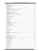
Table of Contents 1 Introduction.................................................................................................................................5 How to Use This Manual.............................................................................................................................. 5 Warning Statements .................................................................................................................................... 5 Caution Statements .........................
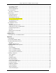
Halogen Gas Monitor – MultiZone Remote Display Setting the Clock .................................................................................................................................... 19 Navigating to the 1st RDM Setup Screen ............................................................................................... 19 Number of HGM Units ............................................................................................................................ 20 HGM Baud Rate ..........
Halogen Gas Monitor – MultiZone Remote Display Responding to Alarms ............................................................................................................................ 34 Alarm Detail Screen ............................................................................................................................... 35 Acknowledging Alarms ...........................................................................................................................
Halogen Gas Monitor – MultiZone Remote Display Release Service Mode Register ......................................................................................... 61 HGM-300 Service Mode......................................................................................................................... 61 PPM Register ................................................................................................................. 62 Zone Log Registers ...............................................
Halogen Gas Monitor – MultiZone Remote Display 1 Introduction How to Use This Manual Thank you for investing in a Bacharach HGM-RD Refrigerant Gas Remote Display Module. To assure operator safety and the proper use of the HGM-RD please read, understand, and follow the contents of this manual, which provides important information on the installation, operation, and maintenance of the monitor. If you have a working knowledge of refrigerant monitors, you will find this manual useful as a reference tool.
Halogen Gas Monitor – MultiZone Remote Display Safety Precautions AC Power Supply The HGM-RD uses a universal power supply that is capable of accepting inputs of 100 to 240 VAC, 50/60 Hz. Ensure the source voltage matches the voltage of the product before energizing the equipment. It is highly suggested that the HGM-RD be placed on its own circuit with UPS or surge protection. Protective Grounding Under no circumstances should the HGM-RD be operated without connection to a protective ground.
Halogen Gas Monitor – MultiZone Remote Display Functional Overview General Description Refrigerant monitors are specified to support compliance to federal, state and local safety codes governing refrigerant emissions. Avoiding significant refrigerant loss reduces equipment replacement costs, maintains equipment efficiency, promotes safety, and protects the environment.
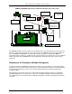
Halogen Gas Monitor – MultiZone Remote Display HGM-MZ / HGM-RD Refrigerant Gas leak Monitor Mechanical Room Placement Aux. Horn/Strobe Fresh air purge from area away from refrigerant gas Exhaust Outside Hallway Sample Inlet HGM-RD Remote Display Module outside of mechanical room Machine Room HGM-MZ Halogen Gas Monitor Chiller Sample Inlet Pickup Points The HGM-RD should be mounted outside of the mechanical room or at least just inside of a door to the room.
Halogen Gas Monitor – MultiZone Remote Display 2 Installation HGM-RD Oblique Photo Upper Mounting Bracket (TBD) Lower Mounting Bracket Instruction 3015-5157 9
Halogen Gas Monitor – MultiZone Remote Display Installation Considerations Warnings and Cautions WARNING: Electrical installation should be performed by a certified electrician, and should comply with all applicable NEC/CEC and local electrical safety codes. WARNING: The AC power ground wire must first be connected to the monitor’s ground stud. Under no circumstances should this monitor be operated without a protective ground.
Halogen Gas Monitor – MultiZone Remote Display Mounting Instructions The HGM-RD should be installed plumb and level and securely fastened to a rigid mounting surface. The enclosure utilizes keyhole mounting brackets designed for ¼ inch fasteners. Locate the four screws as shown in the diagram below or by using the provided mounting template. Allow the screw heads to protrude approximately 1/4".
Halogen Gas Monitor – MultiZone Remote Display Interior Schematic Microcontroller Board CPU Reset Switch TO HOST AC IN Connector T5 Relay Connectors (1 & 2) Instruction 3015-5157 Main Board TO MONITORS RS-485 to HGM-MZ Monitors RS-485 to Building Management System 12
Halogen Gas Monitor – MultiZone Remote Display Electrical Wiring The HGM-RD uses a universal power supply that is capable of accepting inputs of 100 to 230 VAC, 50/60 Hz. The monitor’s power consumption is 25 Watts. It is highly recommended that the monitor be connected directly to the AC power source, preferably on its own circuit. The AC power connection should be completed with UL approved 3-conductor wire (14−18 AWG), rated 300 VAC at 105°C.
Halogen Gas Monitor – MultiZone Remote Display Communication Connections HGM-MZ Network The HGM-RD is connected to the HGM-MZ using a shielded twisted pair instrument cable. The maximum distance between the furthest away HGM-MZ and HGM-RD is 4500 feet. Use any of the remaining service knockouts to gain access to the interior of the monitor.
Halogen Gas Monitor – MultiZone Remote Display Changing Terminator Switch Settings The terminator switch for the RS-485 “TO MONITORS” connector is shipped from the factory in the terminated or “IN” position. This is the correct setting if the HGM-RD is connected to only one HGM-MZ, or if it is the last device on a network chain. If the HGM-RD is being installed in the middle of a network, the terminator must be moved to the “OUT” position. Refer to Multiple HGMs on Page 20.
Halogen Gas Monitor – MultiZone Remote Display Connecting External Alarms Overview Two SPDT relays are available for the connection of external alarm devices. These alarms are useful for alerting the user to global conditions anywhere on the network. Each relay can be programmed to respond to alarm, fault, or ready conditions. Connection Use the AC conduit or any of the remaining service knockouts to gain access to the interior of the HGM-RD.
Halogen Gas Monitor – MultiZone Remote Display 3 Operation HGM-Remote Display The HGM-RD displays comprehensive information about the HGM-MZ network status and enables complete programming control of all system operations. Display Screen A back-lit LCD ESC Key Press to cancel an action. LED Indicators: Cursor Keypad Arrow keys: Permit navigation from screen to screen & data selection & entry.
Halogen Gas Monitor – MultiZone Remote Display Screen Displays When first powered up, a splash screen appears indicating the firmware revision number. After a brief moment the System Screen is displayed. There is a 15-minute warm-up period after power is first applied. Under “HGMS” Monitors, "WARM UP" is displayed. The green indicator on the HGM will blink during the warm-up period. (true?) IMPORTANT: DO NOT block the gas-sample hose or inlet port of any zone.
Halogen Gas Monitor – MultiZone Remote Display Setup Programming Setting the Clock On the System Screen, use the UP/DOWN arrow keys to select date and time. Press the ENTER key to access the Clock setup screen. Clock Setup Screen Use the LEFT/RIGHT cursor keys to move the cursor across the field to the value you wish to edit. Use the UP/DOWN cursor keys to modify the field value and press the ENTER key to accept your entries.
Halogen Gas Monitor – MultiZone Remote Display Number of HGM Units This is the number of HGM-MZ monitors connected to the HGM-RD. 1. Press the ENTER key to select. “NUM MONITORS” will flash. 2. Use the UP/DOWN cursor keys to modify the setting. 3. Press ENTER to accept the new entry or ESC to revert to the previous setting. NOTE: When first powered up, the HGM-RD will automatically detect all HGM-MZ’s on the network with unique node addresses. Refer to HGM Node Address on Page 22.
Halogen Gas Monitor – MultiZone Remote Display Navigating to the 2nd RDM Setup Screen On RDM Setup Screen #1, select MORE to access RDM Setup Screen #2. Select BACK to return to RDM Setup Screen #1. RDM Setup Screen #1 RDM Setup Screen #2 Setting Relay Parameters This setting determines the function of relays 1 and 2 mounted inside the RDM unit. 1. Press the ENTER key while the relay parameter you want to adjust is highlighted. 2.
Halogen Gas Monitor – MultiZone Remote Display Navigating to the 1st and then 2nd HGM Setup Screen From the System Screen, select the HGM-MZ you wish to set up. Press the ENTER key to access that unit’s HGM Setup Screen #1. System Screen HGM Setup Screen #1 On HGM Setup Screen #1, select the SETUP option to go to HGM Setup Screen #2. To return to the System Screen, press ESC. HGM Setup Screen #2 Location This is the name you assign to the HGM-MZ to identify its location.
Halogen Gas Monitor – MultiZone Remote Display Page 27). The monitor will perform a self-check on power-up, and if the number of zones detected does not agree with the number of zones installed a fault will occur. 1. Press the ENTER key to modify the number. 2. Use the UP/DOWN cursor keys to modify the number. 3. Press ENTER to accept the new number or ESC to revert to the previous setting. NOTE: The HGM-MZ auto setting detects the number of zones present on power-up. DO NOT BLOCK ANY ZONES.
Halogen Gas Monitor – MultiZone Remote Display Re-Zero Mode This parameter defines the frequency at which the instrument re-zeros the optical sensor. 1. Press the ENTER key to modify the setting. 2. Use the UP/DOWN cursor keys to toggle between settings. AUTO – Sets the instrument to re-zero every 10 minutes. ZONE CHANGE – Sets the instrument to re-zero at each zone change. This is the most accurate setting but increases the time interval between measurement cycles. 3.
Halogen Gas Monitor – MultiZone Remote Display Zone Setup Programming Navigating to the 1st Zone Setup Screen On the System Screen, select the monitor in the zone you wish to modify and press ENTER. The Montior screen for the selected zone will be displayed. On this screen, select ZONES. System Screen Monitor Screen The Zone Setup screen will be displayed. To return to the System Screen, press ESC. Zone Setup Screen #1 Location This is the name you assign to the monitoring zone.
Halogen Gas Monitor – MultiZone Remote Display Refrigerant This is the type of refrigerant gas being monitored. 1. Press the ENTER key to adjust the setting. 2. Use the UP/DOWN cursor keys to scroll through the list of gas types. 3. Press ENTER to accept the entry or ESC to revert to the previous setting. Distance This is the tubing length in feet from the HGM-MZ to the termination of the air intake line. This value may range from 0 to 500 feet. The default value is 100 feet.
Halogen Gas Monitor – MultiZone Remote Display Navigating to the 2nd Zone Setup Screen On Zone Setup Screen #1, select MORE to access Zone Setup Screen #2. Select BACK to return to Zone Setup Screen #1. To return to the System Screen, press ESC. Zone Setup Screen #1 Zone Setup Screen #2 Leak Level This is the concentration level in PPM that will activate a leak alarm condition. 1. Press the ENTER key to adjust the value. 2. Use the UP/DOWN cursor keys to modify the setting. 3.
Halogen Gas Monitor – MultiZone Remote Display Navigating to the Trend Screen (No Trend text in this doc. Following text was taken from the MZ manual.) On Zone Setup Screen #2, select the Trend option on the bottom left side to access the Trend screen. Zone Setup Screen #2 Trend Screen The trend graph opens with the cursor located over the most recent data point. Use the LEFT/RIGHT cursor keys to move the cursor to different data points.
Halogen Gas Monitor – MultiZone Remote Display 4 General Operation Functional Overview Normally each HGM-MZ will sequentially perform measurements on its active zones without user input. The total time it takes an HGM-MZ to complete a measurement cycle is directly proportional to the number of active zones and the physical length of the air lines. Monitors linked together on a network operate independently of each other and consequently complete their respective measurement cycles at different rates.
Halogen Gas Monitor – MultiZone Remote Display Alarm Conditions When an alarm condition is detected anywhere on the network the red ALARM LED will glow. Additionally, an external alarm device may activate and an audible alarm may sound if those features have been enabled (Pages 21 & 25). An inverse flashing box indicates an alarm condition in the affected zone.
Halogen Gas Monitor – MultiZone Remote Display The System Screen The System Screen provides a summary view of the entire HGM-MZ network. The boxes on the left side of the screen indicate the status of each HGM-MZ monitor. This includes the name, the current zone, and if fault or alarm conditions are present on the network. System Screen Alarm Conditions When an alarm condition is detected anywhere on the network the red ALARM LED will glow.
Halogen Gas Monitor – MultiZone Remote Display Alarm Log On the System Screen, select the HGM-MZ unit you wish to view and press ENTER. System Screen HGM Setup #1 Screen Select the ALARM EVENT LOG option and press ENTER to display the Alarm Log Screen. Alarm Log Screen L=LEAK S=SPILL E=EVACUATE Use the LEFT/RIGHT and UP/DOWN cursor keys to move through the log. The Alarm log shows the last 20 alarm events.
Halogen Gas Monitor – MultiZone Remote Display Fault Conditions If a system malfunction occurs, the yellow FAULT LED will glow. Additionally, an external alarm device may activate and an audible alarm may sound if those features have been enabled (Pages 21 & 25). The FAULTS box on the right of the screen will blink and then counts the number of HGM units on the system with a fault. To investigate a fault, select the FAULTS option to go to the Fault Screen (Page 31).
Halogen Gas Monitor – MultiZone Remote Display Alarms Functional Overview If the PPM level for any zone exceed its designated spill, leak, or evacuate thresholds, an alarm condition will be created. Once the HGM-MZ completes a measurement cycle in the affected zone the alarm condition will be indicated. At that time the red ALARM LED on the HGM-MZ will glow. Additionally, an external alarm device may activate and an audible alarm may sound if those features have been enabled (Pages 21 & 25).
Halogen Gas Monitor – MultiZone Remote Display Alarm Detail Screen To further investigate an alarm, select the alarm on the Alarm Summary screen, then press ENTER to access the Alarm Detail Screen.
Halogen Gas Monitor – MultiZone Remote Display Acknowledging Alarms Each pending alarm may require, depending upon selected alarm mode, acknowledgment before the system returns to normal operation (refer to Alarm Ack Mode on Page 25). To acknowledge an alarm, navigate to the Alarm Detail Screen and press the ACK key as previously described.
Halogen Gas Monitor – MultiZone Remote Display The Trend Screen Overview - Log Interval The HGM-MZ retains a data log of 100 measurements for each zone. The log interval is the number of minutes from 1 to 1440 between each log point. This parameter can be changed from Zone Setup Screen #1 (Page 27). The default setting for this parameter is 1440 minutes (24 hours). If the log interval time is set to 0, then a measurement is recorded in the trend log after every measurement cycle.
Halogen Gas Monitor – MultiZone Remote Display System Faults Functional Overview If a system malfunction occurs, the HGM-MZ will detect the problem and cause its yellow FAULT LED to glow. Additionally, an external alarm device may activate and an audible alarm may sound if those features have been enabled (Pages 21 & 25). The next time the HGM-RD polls the affected monitor its yellow FAULT LED will also glow.
Halogen Gas Monitor – MultiZone Remote Display • REZERO VOLT TOL – The detector output voltage is out of tolerance. Check the Diagnostic Screen as in item 4 and contact the factory for assistance. • TRIGGER FAULT – No trigger from IR source pulser. Contact factory with all information from the DIAGNOSTIC SCREEN for farther instructions. NON CRITICAL FAULTS • BOX TEMP FAULT – Enclosure’s internal temperature is outside normal range (or IR sensor has failed).
Halogen Gas Monitor – MultiZone Remote Display Clearing System Faults If the fault condition is associated with an HGM-MZ, the monitor will return to normal operation soon after the problem is corrected. At that time the YELLOW LED will turn off and any external alarms connected to the monitor’s alarm relays will also turn off. The HGM-RD will return to normal operation the next time it polls the affected HGM-MZ monitor.
Halogen Gas Monitor – MultiZone Remote Display The Calibration Screen Overview The Calibration Screen is used to adjust the calibration factor for each refrigerant gas. It is also used to program the instrument for new gasses. IMPORTANT: Changing information on CAL FACTORS will VOID the factory calibration. Typically, the unit will remain within the factory-calibrated accuracy indefinitely and no calibration is required.
Halogen Gas Monitor – MultiZone Remote Display Calibration Procedure on Main Monitor The CAL FACTOR is determined by sampling a known dilution of the type of refrigerant gas to be sampled. The sample must be prepared to less than half the desired accuracy and the concentration must be corrected for ambient temperature and pressure at the time of measurement. Calibration is best performed at or near full scale (1,000 PPM).
Halogen Gas Monitor – MultiZone Remote Display 1. Select the CUSTOM option to assign a name to the refrigerant. a. Use the LEFT/RIGHT cursor keys to move across the entry field and the UP/DOWN cursor keys to modify the individual characters. b. Press ENTER to accept the new entry or ESC to revert to the previous setting. 2. Enter the new CAL Factor as received from Bacharach.
Halogen Gas Monitor – MultiZone Remote Display Diagnostic Screen Overview The Diagnostic Screen contains sensor data and status information useful for trouble shooting various fault conditions. An explanation of each line is given below along with normal operating ranges. LINE 1: Detector Voltage – This is the peak-to-peak output of the IR sensor, in the absence of refrigerant this value can range from 3.900V to 4.500V.
Halogen Gas Monitor – MultiZone Remote Display Service Mode When activated, the Service Mode will disable a specific HGM-MZ unit for a specified length of time. The default is 60 minutes. This time interval can be changed as described in the Service Timeout section on Page 26. IMPORTANT: Note that while in the Service Mode, no measurements are made, nor are alarms activated. (I couldn’t get this to work, so I need definition on this section.
Halogen Gas Monitor – MultiZone Remote Display 5 Maintenance Warnings and Cautions WARNING: Shock hazard! Always disconnect AC power before working inside the monitor. CAUTION: The HGM-RD contains sensitive electronic components that can be easily damaged. Be careful not to touch or disturb any of these components. Servicing Air Lines & Termination Filters System air lines (P/N 3015-3235) should be checked periodically for obvious signs of kinks, damage, and contamination.
Halogen Gas Monitor – MultiZone Remote Display Appendix Logic Diagram Instruction 3015-5157 47
Halogen Gas Monitor – MultiZone Remote Display Recommended Alarm Settings Refrigerant Leak PPM Spill PPM Evacuate PPM Decimal Hex R11 100 300 500 0 00 R12 100 300 500 1 01 R22 100 300 500 2 02 R23 100 300 500 3 03 R113 100 300 500 4 04 R114 100 300 500 5 05 R123 25 35 35 6 06 R124 100 300 500 7 07 R134A 100 300 500 8 08 R401A 100 300 500 9 09 R402A 100 300 500 10 0A R402B 100 300 500 11 0B R404A 100 300 500 12 0C R407A 100
Halogen Gas Monitor – MultiZone Remote Display RS-485 Communication Protocol Overview The following instructions are intended as a guide for integrating the HGM-MZ network into a Building Management System. If you are unfamiliar with complex systems of this type, it is recommended that you contact Bacharach for technical assistance. MODBUS RTU Protocol The HGM-MZ monitor communicates with master devices (such as the HGM-RD or a Building Management System) over the RS-485 serial interface.
Halogen Gas Monitor – MultiZone Remote Display HGM-MZ MODBUS RTU Operation Overview The HGM-400 and HGM-RD are equipped to communicate with other equipment using the MODBUS RTU protocol. Using this communication channel a MODBUS master device may communicate with up to 15 HGM-MZ’s on a communications network, exchanging measurement information, alarm data, fault data, history (logs and trends) and setup information.
Halogen Gas Monitor – MultiZone Remote Display and registers are used to communicate with the HGM-MZ directly or through the HGM-RD. If the communications is through the HGM-RD, it monitors each MODBUS message to determine if the message is intended for one of the HGM-MZ’s it is connected to. If it is, the HGM-RD passes the message through to the HGM-MZ’s. If it is not, the message is not passed through. The HGM-RD does not make any modifications to MODBUS messages.
Halogen Gas Monitor – MultiZone Remote Display Summary of Registers Register Name Number HEX Decimal Description System Data 0x0010 16 R/W HGM System Setup Data Status 0x0011 17 R/W Operating summary of faults, alarms and status Zone Data 0x12xx 4609 4630 R/W Setup data for up to 16 zones (xx defines zone number) CAL Data 0x0014 20 R/W Cal Factors for all gases Date/Time 0x0015 21 R/W Set HGM-MZ date & time Sensor Data 0x0016 22 R Raw measurement of sensors Rel.
Halogen Gas Monitor – MultiZone Remote Display System Data Register Register 0x0010h R/W 54 bytes Variable Type Length Description Type UI 2 bytes Indicates EEPPROM has been initialized if value = 300 DO NOT MODIFY REV Float 4 bytes Firmware Rev Level DO NOT MODIFY SN UI 2 bytes Firmware Serial Number DO NOT MODIFY Node UC 1 byte Network Slave Node # (valid values are 1-15). The default is that indicated by the Node DIP Switch on main board.
Halogen Gas Monitor – MultiZone Remote Display Status Register Register 0x0011h R/W 10 bytes Variable Type Length Description Mode UC 1 byte Defines Operating Mode of HGM-400. 0 = normal Mode; 1 = Zone_Hold Mode; 2 = Diagnostic Mode; 3 = Service mode. DO NOT MODIFY (use zone hold register or service mode register to change this parameter) State UC 1 byte Defines HGM-400 Current State.
Halogen Gas Monitor – MultiZone Remote Display Zone Data Register 0x12xxh R/W 78 bytes Each zone for an HGM-MZ has a separate Zone data structure that is 78 bytes long. The zone number is the low order byte in the register address (i.e., Zone 1 data register = 0x1201h) Variable Type Length Description Location C 13 bytes 13 byte array, Alpha Numeric Description or Name of Zone Flow OK UC 1 byte Status of Flow check. Value of 1 indicates flow check is good. DO NOT MODIFY Refrig.
Halogen Gas Monitor – MultiZone Remote Display Notes on Alarms and Alarm Acknowledge The HGM-MZ can be operated in two different alarm acknowledge modes, Auto and Manual (set via the alarm_ack_mode variable in the system data register). For purposes of this discussion, the term “Alarm” refers to a HGM-MZ state where the alarm light is on and the appropriate alarm relay is activated. The term “Alarm condition” refers to the external condition (i.e.
Halogen Gas Monitor – MultiZone Remote Display Cal Data Register Register 0x0014h R/W 174 bytes Variable Type Length Description Factor Float 132 bytes 33 element array containing cal factors for each of the 33 gases.
Halogen Gas Monitor – MultiZone Remote Display Sensor Data Register Register 0x0016h R Variable Type Pressure Float 4 Manifold Pressure is PSIA P_Volts Float 4 Pressure sensor output Voltage Vacuum_P Float 4 Pressure with all value closed and pump on in PSIA Ambient_P Float 4 Absolute Ambient Pressure in PSIA Box_T Float 4 Enclosure Temperature in Degrees C Box_T_Volts Float 4 Box temp sensor output voltage Bench_T Float 4 Optical bench temperature in Degrees C Bench_T_Volts
Halogen Gas Monitor – MultiZone Remote Display Release Zone Hold Register Variable Rel_Hold Type Length * * Hold Zone Register Variable Zone_Hold Type Register 0x0017h W Description See description of STATUS REGISTER Register 0x0018h W Length * * 10 bytes 10 bytes Description See description of STATUS REGISTER HGM-300 Hold Mode The HGM-400 can be made to hold or “dwell” on a particular zone if necessary.
Halogen Gas Monitor – MultiZone Remote Display Fault Log Register Register 0x1900, 0x1901h R 302 bytes These registers contain the 20 most recent fault events, the time they occurred, and a pointer to the most recent event. The data is split into 2 registers. The first register contains 200 bytes and the second register contains 102 bytes.
Halogen Gas Monitor – MultiZone Remote Display Service Mode Register Variable Rel_Svc_Mode Type Register 0x001Bh W Length * * Description See description of STATUS REGISTER Release Service Mode Register Register 0x001Ch W Variable Ent Svc_Mode Type Length * * 10 bytes 10 bytes Description See description of STATUS REGISTER HGM-300 Service Mode The HGM-400 can be placed into service mode if necessary.
Halogen Gas Monitor – MultiZone Remote Display PPM Register Register 0x001Eh R 32 bytes Variable Type Length Description PPM UI 32 bytes 16 Unsigned Integers that represent the PPM values for each HGM-MZ zone NOTE: 16 values are returned independent of the number of actual zones installed in the unit. The master device is required to know how many zones are installed in the unit (available in the System Register) in order to properly interpret the data.
Halogen Gas Monitor – MultiZone Remote Display Specifications HGM-RD Specifications Product Description The HGM-RD Remote Display Module provides remote programming, interrogation and display functionality to support the HGM-MZ0 Refrigerant Gas Monitor. The system design supports compliance to the refrigerant monitoring requirements of ANS/BSR ASHRE 15-1994. Inputs The HGM-RD accepts inputs from up to four HGM-MZ monitors.
Halogen Gas Monitor – MultiZone Remote Display Headquarters: 621 Hunt Valley Circle, New Kensington, PA 15068 Website: www.bacharach-inc.com • E-mail: help@bacharach-inc.com Printed in U.S.A. Instruction 3015-4148 ® Registered Trademark of Bacharach Inc.