GALAXY® II Gateway Receiver Fixed Network need new picture GXY-UM-00760-EN-FCC (February 24, 2014 11:13 AM) Installation Manual
GALAXY® II Gateway Receiver Page ii February 2014
Installation Manual CONTENTS OVERVIEW . . . . . . . . . . . . . . . . . . . . . . . . . . . . . . . . . . . . . . . . . . . . . . . . . . . . . . . . . . . . 5 Product Description . . . . . . . . . . . . . . . . . . . . . . . . . . . . . . . . . . . . . . . . . . . . . . . . . . . . 5 License Requirements . . . . . . . . . . . . . . . . . . . . . . . . . . . . . . .
GALAXY® II Gateway Receiver Page iv February 2014
Installation Manual OVERVIEW This manual contains installation and programming instructions for the GALAXY® II gateway receiver. Proper performance and reliability of the gateway receiver depends upon installation in accordance with these instructions. Product Description The GALAXY II gateway receiver (“gateway”) is an easy-to-install, easy-to-deploy unit that collects metering data from the GALAXY TR3 meter endpoints in the area.
GALAXY® II Gateway Receiver SPECIFICATIONS IIMPORTAN The GALAXY II gateway receiver is functionally equivalent to the previous GALAXY gateway receiver. However, the physical configuration of the new enclosure is different. This change affects installation considerations, including cabling, size, weight and wind load area. Make sure to consider these variables in your evaluation of an installation location. Installation 1.25…2.5" outside diameter pole mount: Aluminum V-blocks 2.
Installation Manual TYPE OF INSTALLATION New If this is a new installation, follow the installation procedures in this document, beginning with "Mounting the Gateway" on page 8. Replacement If this is a replacement of an existing GALAXY gateway receiver, review the following information before starting installation. • Verify that your existing infrastructure is rated for the weight and wind load area of the gateway. • GALAXY Gateway Receiver 3.0 GALAXY II Gateway Receiver Weight 6.5 lb 11.
GALAXY® II Gateway Receiver MOUNTING THE GATEWAY IMPORTANT Receiver installation, mounting and disposal shall be in accordance with all local, state and federal regulations. When installing the receiver, customer is responsible for complying with local, state, and federal codes and guidelines, as well as applicable industry standards, such as ANSI/TIA/EIA 222 (structural standards for steel antenna towers and antenna supporting structures) and the National Electrical Code (NEC).
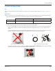
Installation Manual Gateway Standard Components • One GALAXY II gateway receiver with attached mounting backplate and antennas. • V-block clamps or banding and locking equipment for attaching a gateway receiver to a pole. • 100-foot or 300-foot power cable, M12 connector, AC-to-DC power supply and power cord.
GALAXY® II Gateway Receiver Tools and Materials (customer-supplied) • Precision slotted screwdriver 2.4 mm (0.
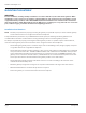
Installation Manual Lock Washer Lock Washers Nuts Bolts Clamps Figure 6: Receiver positioning and clamps 7. Place a lock washer and nut on each bolt and tighten the nuts 100…150 inch-pounds to ensure the gateway is sufficiently secured to the pole. 8. Repeat Steps 6 and 7 for attaching the V-block clamp mounting bracket hardware to the bottom bolts of the gateway mounting backplate.
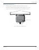
GALAXY® II Gateway Receiver Banding Mounting Banding mounting equipment is sized to mount the gateway on a 2-1/2…24-inch outer diameter pole. IMPORTANT When using the banding mounting kit for the network gateway receiver, use BAND-IT® Idex installation practices. Refer to www.band-it-idex.com/en/Literature/Tool_Instructions/P05886.pdf for more information.
Installation Manual 1. Locate the BAND-IT tool and supplied installation instructions. 2. Follow the BAND-IT-supplied installation instructions enclosed with the BAND-IT tool for attaching the network gateway receiver to a pole. 3. Using a 1/2-inch wrench, the recommended torque for the 5/16-24 screw that attaches the gateway bracket to the BAND-IT banding is 144…168 inch-pounds (12…14 foot-pounds).
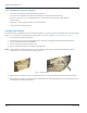
GALAXY® II Gateway Receiver ELECTRICAL CONNECTIONS AC Power Badger Meter provides an AC-to-DC power supply with power cord that plugs into a standard three-prong 120V AC outlet. If powering the gateway directly via DC power, please refer to the DC power information on page 19. Figure 11: 120V AC power supply with power cord M12 Connector Assembly NNOTE: Use only approved Badger Meter power cable, 100-feet (66233-010) or 300-feet (66233-013) for this assembly.
Installation Manual Figure 13: Stripped cable wires 3. Shorten the foil shield flush with the outer jacket. 4. Strip the ends of the six (6) colored wires to a length of 1/8 inch. Twist the conductors on each wire. 5. Shorten the drain/bare wire (no insulation) to 11/16 inch. 6. Loosen each screw (about 2…3 turns) on the female insert and attach the wires to the insert using the chart below. Retighten each screw after the wire has been connected.
GALAXY® II Gateway Receiver Figure 15: Bottom of gateway receiver 8. Remove the M12 cap from the M12 receptacle on the bottom of the network gateway receiver and discard the cap. 9. Connect the M12 plug connector assembly to the M12 receptacle and tighten the locking ring in a clockwise direction until finger tight. 10. Connect the 308 connector on the other end of the power cable to the 308 connector of the AC-to-DC power supply and snap the anti-tamper collar over the connection. 11.
Installation Manual ELECTRICAL / NETWORK INSTALLATIONS Access to Power • The gateway requires access to power and can use either a 120V AC grounded outlet for use with the AC-to-DC power supply and power cord (66528-003), or a DC power source to be used with the DC power source cable with 308 in-line connector. For a gateway with a LAN PoE configuration, a Power over Ethernet connection is required.
GALAXY® II Gateway Receiver LAN Recommended Installation NNOTE: Consult manufacturer's installation and usage recommendations as well as appropriate codes, regulations and standards for the LAN RJ45 Ethernet connection.
Installation Manual DC Power Source Installation The gateway can be ordered with a 10-foot DC power source cable (66233-020) for direct connection with a customer-supplied DC power source. The power requirements for the gateway are a DC voltage source between 12…24 V DC. Power cable lengths may be limited by the voltage of the DC source.
GALAXY® II Gateway Receiver External DC Power Source Connections Wire Color for 66233-020 External DC Power Source Page 20 Drain (no insulation) Negative (–) Black Negative (–) Brown Not needed/cut off Red Positive (+) Light Blue Not needed/cut off February 2014
Installation Manual RJ45 Plug Assembly (for LAN connectivity only) NNOTE: Do not use a serial-to-LAN adapter! Figure 21: Serial-to-LAN adapter kit Required Supplies: • RJ45 Plug Assembly (66527-001) • Ethernet cable cord set using outdoor rated Cat.5e cable and RJ45 jack (customer supplied) • Wrenches, 1-1/16 inch (customer supplied) Metallic Housing Insulator Insert Halves Cable Gland Figure 22: RJ45 plug components 1. Feed the cord set cable through the dome nut end of the cable gland. 2.
GALAXY® II Gateway Receiver Figure 24: RJ45 plug assembly with Code A orientation 4. Insert the insulator assembly into the metallic housing using the Code A orientation as shown in Figure 24. You will hear a ”click“ to confirm a complete connection. NNOTE: Code A orientation must be used or the plug will not fit into the receptacle. Assembled RJ45 plugs cannot be disassembled without a special tool (67163-001) and must be replaced. 5.
Installation Manual INTENTIONAL BLANK PAGE February 2014 Page 23
GALAXY is a registered trademark of Badger Meter, Inc. Other trademarks appearing in this document are the property of their respective entities. Due to continuous research, product improvements and enhancements, Badger Meter reserves the right to change product or system specifications without notice, except to the extent an outstanding contractual obligation exists. © 2014 Badger Meter, Inc. All rights reserved. www.badgermeter.