PRELIMINARY A29799 RML November 2007 First InterComm™ System Installation Guide www.Firstintercomm.
PRELIMINARY A29799 RML November 2007 © 2007, BAE Systems Information and Electronic Systems Integration Inc..
First InterComm™ System Installation Guide Table of Contents List of Illustrations ....................................................................................................... iii List of Tables ................................................................................................................ iii Document Change History .......................................................................................... iii Warnings and Precautions ............................................
First InterComm™ System Installation Guide Table of Contents (Cont.) Appendix - B VCA100 Software Programs and Utilities........................................... 18 B.1 BAE Systems VCA Management Program................................................. 18 B.2 Serial IP Program ....................................................................................... 19 Appendix C - Acronyms and Abbreviations..............................................................
First InterComm™ System Installation Guide List of Illustrations 1 2 3 4 5 6 B-1 B-2 B-3 Typical VCA100 Vehicle Installation ..................................................................... 2 First InterComm VCA100 Unit .............................................................................. 3 VCA100 Power Harness Connector – Front View ................................................ 4 Standard Comtelco WiFi Antenna ........................................................................
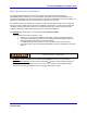
First InterComm™ System Installation Guide Warnings and Precautions Federal Communications Commission (FCC) Compliance - This equipment has been tested and found to comply with the limits for a Class B digital device, pursuant to Part 15 of the FCC Rules. These limits are designed to provide reasonable protection against harmful interference in a residential environment.
First InterComm™ System Installation Guide EMC Installation Guidelines The design and manufacture of the VCA100 conforms to the appropriate Electromagnetic Compatibility (EMC) standards, but correct installation is required to ensure that performance is not compromised. Although every effort has been taken to ensure that it will perform under all conditions, it is important to understand what factors could affect the operation of the product.
First InterComm™ System Installation Guide 1.0 Introduction The First InterComm™ System (FICS) allows first responders from different agencies at an emergency incident to readily communicate with one another, even though their radios operate on different frequencies; i.e., VHF, UHF or 800 MHz systems, both digital and analog. The FICS can accommodate any new communication technologies, including the 700-MHz bandwidth.
First InterComm™ System Installation Guide The system operates on 12VDC vehicle power through an independent cab-mounted switch. There are no speakers, microphones, or other vehicle tie-ins. Nine VCA100 models are available to cover the LMR bands (see Table 1). The LMR antenna must match the frequency band of the VCA100 model being installed. A standard, roof mounted 2.4 GHz 802.11 antenna is used for all VCA100 models. Figure 1.
First InterComm™ System Installation Guide Table 1. First InterComm VCA100 Models Model VCA100-L1FCGX VCA100-L2FCGX VCA100-V1FCGX VCA100-V1PCGX VCA100-V1PAGX VCA100-V1PDGX VCA100-U1FCGX VCA100-81FCGX VCA100-81PCGX VCA100-81PDGX VCA100-91FCGX 2.1 Protocol FM FM FM FM/P25 FM/P25 FM/P25 FM FM FM/P25 FM/P25 FM Encryption None None None None DES/AES DES None None None DES None LMR Band VHF Low Band VHF Low band VHF High Band VHF High Band VHF High Band VHF High Band UHF 800 800 800 900 Frequency Range 29.
First InterComm™ System Installation Guide 2.2 VCA100 Power Connector The VCA100 uses three pins of a 6-pin Molex connector as shown in Figure 3. NC Gnd NC 4 5 6 1 2 3 +12 VDC Pwr +12 VDC Sense Front View of Molex Connector NC Figure 3. VCA100 Power Harness Connector – Front View 2.3 WiFi Antenna The standard WiFi antenna for all VCA100 installations is the Comtelco Model A10245B (Figure 4), a 2.4 GHz 802.
First InterComm™ System Installation Guide 3.0 Planning the Installation 3.1 Installation Kit Components Table 2 lists the deliverable installation kit for the First InterComm system. Specific antennas will vary depending on the LMR frequency. The material listed is based on availability; equivalent products may be used. Table 3 lists typical Installer-supplied parts that are vehicle specific and not supplied with the kit. Table 2.
First InterComm™ System Installation Guide 3.2 Tools and Test Equipment Table 4 lists details of the test equipment and software required to install the FICS. These comprise: • A laptop computer equipped with WiFi capability, loaded with Windows® XP1 Operating System, Service Pack 2, and FICS installer software (required to upload user-specific parameters into the VCA100). The laptop is also used to test the FICS after installation.
First InterComm™ System Installation Guide 3.3 System Component Locations WARNING WHEN SELECTING LOCATIONS FOR FIRST INTERCOMM COMPONENTS, AVOID HIGH FREQUENCY (HF) NOISE PRODUCERS AND DO NOT RUN DC POWER FEEDS TO THE VCA100 PARALLEL TO IGNITION CIRCUITS, ELECTRONIC MODULES, OR SIMILAR ITEMS. AVOID RUNNING POWER LEADS IN PARALLEL WITH VEHICLE WIRING OVER LONG DISTANCES. 3.3.1 VCA100 The VCA100 has no operator interfaces other than an activity indicator.
First InterComm™ System Installation Guide 3.3.3 Land Mobile Radio Antenna The LMR antenna must match the frequency of the specific VCA100 model being installed on the vehicle. Ensure that the new LMR antenna is not installed in close proximity to any existing LMR antennas. We recommend keeping the antenna at least 12 inches away from any light bars, antennas, or other roof-mounted equipment and MUST be installed so as to provide a separation distance of at least 18 inches (45 cm) from all persons. 3.3.
First InterComm™ System Installation Guide 4.0 Installation Procedures 4.1 VCA100 Unit 1. Record the VCA100 model number and serial number on the INSTALLATION SIGN OFF SHEET (see Appendix E). 2. Carefully inspect the area selected for the VCA100 unit to ensure that the area is free of physical or electrical obstacles that could interfere with proper installation, maintenance, or operation. 3.
First InterComm™ System Installation Guide 5. Connect the WiFi RF cable to the VCA100 NETWORK A SMA connector. Use cable ties and mounts to keep the cable from moving or placing stress on the SMA connector. 4.3 Land Mobile Radio Antenna 1. Carefully inspect the area selected for the LMR antenna to ensure that the area is free of physical or electrical obstacles that could interfere with proper installation, maintenance, or operation. 2.
First InterComm™ System Installation Guide 4.5 VCA100 On/Off Switch 1. Carefully inspect the area selected for the VCA100 On/Off Switch to ensure that the area is free of physical or electrical obstacles that could interfere with proper installation, maintenance, or operation. 2. Drill or cut an area to hold the lighted toggle switch. Mount and label the switch. 3. Locate a suitable chassis ground as close to the new power switch as possible. If necessary, scrape and remove paint to reach bare metal.
First InterComm™ System Installation Guide 5.0 Initial Power Test 1. Before connecting to the VCA100, use a voltmeter at the VCA100 power harness connector to check for a constant +12VDC, switched +12VDC, and ground (Figure 3 shows the VCA100 power connector). 2. Follow the steps as listed in Table 6. Correct any problems encountered before proceeding to the next step. Table 6.
First InterComm™ System Installation Guide 6.0 Update User Specific Parameters The VCA100 is delivered with factory-installed default parameters. After vehicle installation, the unit must be updated with user-specific parameters. This programming is done using BAE Systems’ supplied VCA MANAGEMENT PROGRAM and utilities loaded on a maintenance laptop equipped with a Buffalo Technology WLI-CB-G54HP wireless network card. 6.1 Preparation 1.
First InterComm™ System Installation Guide 6.2 VCA100 Update Procedure 1. Appendix B contains instructions for operating the Serial IP and the VCA MANAGEMENT PROGRAM. 3. Follow the steps as listed in Table 8. Correct any problems encountered before proceeding to the next step. Table 8. VCA100 Update Procedure Required Items: a. VCA100 Installed in vehicle b. User Parameters (Table 7 of this document). c.
First InterComm™ System Installation Guide 7.0 Unit Test Plan Follow the test procedures described in Paragraphs 7.1 and 7.2. Correct any problems found, retest, and record final results on the INSTALLATION SIGN OFF SHEET (Appendix E). 7.1 LMR Antenna VSWR Test Perform an antenna VSWR test using the antenna manufacture’s procedure or a standard industry accepted procedure. Record results in Table 9. Note THIS TEST IS NOT REQUIRED IF THE ANTENNA WAS TERMINATED BY THE OEM AND HAS NOT BEEN MODIFIED.
First InterComm™ System Installation Guide 8.0 Troubleshooting Appendix D contains detailed troubleshooting procedures for the FICS. IMPORTANT 9.0 • If the FICS appears to interfere with incident site operations, immediately turn off every VCA unit (and ICTCS if in use), and return to normal SOP. • If ICTCS or laptop computer problems occur, the VCA100 units will remain in their assigned Talkgroups.
First InterComm™ System Installation Guide Appendix A Recommended LMR Antennas Table A-1.
First InterComm™ System Installation Guide Appendix B VCA100 Software Programs and Utilities B.1 BAE Systems VCA Management Program The VCA Management Program is used to connect wirelessly to the VCA100 in order to change User parameters and upgrade software on the VCA100. The procedure is to: 1. Launch the BAE Systems VCA Management Program software using the Windows start button to navigate to and click on the TBD Icon. 2. Enter password in the pop up window and click Validate. 3.
First InterComm™ System Installation Guide B.2 Serial IP Program Serial IP, a utility program, creates a virtual COM port that associates an IP address with a hardware COM port. This allows RS-232 programming over a wireless link to the VCA100 RF Module. The procedure is to: 1. Start the VCA MANAGEMENT PROGRAM (Paragraph B.1) to enable access to the VCA100. 2. Start the Serial IP Panel (Figure B-2) using the Windows start button; i.e., START Æ ALL PROGRAMS Æ SERIAL IP Æ CONTROL PANEL 3.
First InterComm™ System Installation Guide Figure B-3.
First InterComm™ System Installation Guide Appendix C Acronyms and Abbreviations ABS AES ATC ATO AWG COM DC DES DHS EMI EMS FCC FICS FM GPS GXL HF HSS IAB IAN IC ICTCS ID IP LED LMR MIPT NIMS NMO OEM P25 RF SAE SEL SMA SOP SPST TBD TNC UHF VCA VHF VSWR Antilock Brake System Advanced Encryption Standard Automotive Blade-Type Fuse Automotive Blade-Type Fuse American Wire Gauge Communication (port) Direct Current Data Encryption Standard Department of Homeland Security Electromagnetic Interference Emergency
First InterComm™ System Installation Guide WiFi Page 22 Wireless Fidelity A29799 November 2007
First InterComm™ System Installation Guide Appendix D Troubleshooting Procedures To Be Supplied A29799 November 2007 Page 23
First InterComm™ System Installation Guide Appendix E Installation Sign Off Sheet I CERTIFY THAT THE FIRST INTERCOMM SYSTEM SUPPLIES AND INSTALLATION SERVICES HAVE BEEN FURNISHED IN ACCORDANCE WITH APPLICABLE CONTRACT REQUIREMENTS.
First InterComm™ System Installation Guide THIS PAGE INTENTIONALLY LEFT BLANK A29799 November 2007 Page 25
First InterComm™ System Installation Guide Page 26 A29799 November 2007