
User's Manual


B. Right Turn Signal: Connect the black and green pair of wires to the right turn
signal.
C. Left Turn Signal: Connect the black and brown pair of wires to the left turn signal.
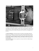
D. Headlight, Flasher, Running Light and High Beam Indicator: Plug the headlight
connector (white three terminal connector) into the back of the headlight. Connect the
yellow and black wire pair to the two wires from the high beam indicator (May be
previously connected). Connect the red/green and orange wires to the flasher. The
red/green wires go to the terminal labeled "P" and the orange wire connects to the
terminal labeled "L". Plug the brown and green wires from the headlight connector
into the matching brown and green wires from the headlight running light.
Note that the headlight bulb is a standard H4 35/35 watt automotive unit. Do not replace
this bulb with a 55/60 watt bulb. The stator does not produce enough power to run this
bulb and the rest of the lighting system without discharging the battery. (See Battery
Maintenance Section).
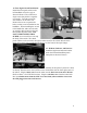
19. Rear Wiring Connections: You will now make all the connections required to the
wiring harness at the rear of the bike. Take your time to do a neat job here so that you
will have a reliable lighting system. Refer to color photographs to copy wiring layout.
If you make a mistake in the following steps, the worst that could happen is the bike will
catch fire and burn to the ground (NOT).
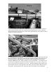
1. Run the red and black leads from the battery around the front right corner of
the airbox. At this time we recommend you remove the fuse from the
rectifier/regulator wiring temporarily until the installation is complete. Plug the
black male lead from the battery into the black female lead from the
rectifier/regulator. Plug the red female lead from the battery into the red
male lead from the rectifier/regulator.
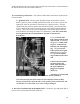
2. Locate the black ground lead from the voltage regulator and install the ring
terminal underneath one of the regulator mounting bolts (if you haven’t done so
already).
In the next few steps we will connect the main gray multi-conductor cable to
the rest of the wiring harness. The end of this cable should be above the
fender in the area behind the airbox as shown in the color photos.
11