Troubleshooting & Service for EL/VS Systems 60 Hz 1
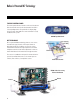
Balboa’s Patented M7 Technology TOPSIDE CONTROL PANEL The control panel activates functions at the touch of a button. Each function will echo from the circuit board to the LCD in a corresponding manner. The panel will also display diagnostic messages that enable the service technician to easily troubleshoot the system. ML700 Top Side Panel M7 TECHNOLOGY M7 is a patented Balboa technology that uses two sensors inserted at the opposite ends of the heater element to determine flow, dry fire conditions, etc.
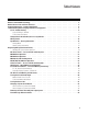
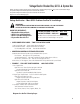
Table of Contents Balboa’s Patented M7 Technology . . . . . . . . . . . . . . Balboa Service Tools and Parts Checklist . . . . . . . . . . . Important Information -- Product Identification . . . . . . . . Troubleshooting & Servicing Spa and Electrical Equipment . . G.F.C.I. Troubleshooting . . . . . . . . . . . . . . . . . If Correct Wiring is Verified . . . . . . . . . . . . . . . To Disconnect the Heater . . . . . . . . . . . . . . . . Voltage Checks: Breaker Box, G.F.C.I. & System Box . . . .
Diagrams (in alphabetical order) 300/300F/500Z Series Panel . . . . . . . . . . . . . . . . . . . . . . . . . . . . . . . . . . . . . . . . . . . . . . . . . .34 500DZ Series Panel . . . . . . . . . . . . . . . . . . . . . . . . . . . . . . . . . . . . . . . . . . . . . . . . . . . . . . .34 500SZ Series Panel . . . . . . . . . . . . . . . . . . . . . . . . . . . . . . . . . . . . . . . . . . . . . . . . . . . . . . .34 Balboa QuickCheckTM Part No. 70002 . . . . . . . . . . . . . . . . . . . . . . . . . .
Balboa Service Tools and Parts Checklist Service Tools Required UÊ UÊ UÊ UÊ UÊ Ammeter (50A) Balboa Six-in-one Screwdriver Digital Multi-meter Padlock (to lock electrical disconnect during service) Pliers: Slip Joint & Needle nose UÊ UÊ UÊ UÊ UÊ Precision Thermometer - Digital Fever Type Quick CheckTM Test Kit Silicone Tube Small Wire Cutters Two 3/8” Open End Wrenches (one wrench should be ground down to 5/32” [0.
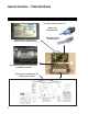
Important Information -- Product Identification Two Types of Plug-in Connectors: “Molex” Type, ML/GL Connector On Every System, an Identification Label Is Placed on top of the Casing Heater Element Specifications Are Shown on the Heater Tube Label On Every System, a Wiring Diagram Is Placed Inside the Door 6 “Phone Plug” RJ Type, VL/GS Connector
Troubleshooting & Servicing Spa and Electrical Equipment HIGH VOLTAGE CAN SERIOUSLY INJURE OR KILL! ONLY EXPERIENCED TECHNICIANS SHOULD SERVICE THIS EQUIPMENT. DO NOT remove the protective covers from any electrical enclosure, or attempt to service any related electrical device, unless you are a qualified electrician or service professional. DANGER Risk of electric shock. Before working with any electrical connections, make certain that the Main Power breaker from the house breaker box has been turned off.
G.F.C.I. Troubleshooting Keep in mind that a majority of G.F.C.I. tripping problems can be attributed to incorrect wiring. G.F.C.I. troubleshooting usually finds the problem. IF CORRECT WIRING IS VERIFIED TO DISCONNECT THE HEATER UÊ Check to see if the proper G.F.C.I. is installed. UÊ Check the label in the system box near TB1 to determine the maximum amperage draw for the system. UÊ Be sure the G.F.C.I. is rated for more amperage than the system will draw. UÊ For a 240 V dedicated system, a 2-pole G.F.C.
Voltage Checks: Breaker Box, G.F.C.I. & System Box When checking for proper voltage, keep in mind that the acceptable voltage range is + 10% of the recommended voltage. Acceptable voltage when 120 V is specified is between 108 and 132 V. Acceptable voltage when 240 V is specified is between 216 and 264 V. Diagrams are on the following pages. Voltage Verification - Most G.F.C.I.
120 Volt Residential Wiring Schematic with G.F.C.I. G.F.C.
Spa System Box 120VAC Service Bottom view of G.F.C.I CLASS G FUSE 30A K6 F5 J73 G C WHT AC J11 J25 J63 J15 J23 W1 NEUTRAL WHITE NEUTRAL WHITE 120/240VAC 16/40A MAX 60Hz HOT BLACK HOT BLACK TORQUE RANGE FOR TB1: 27-30 IN. LBS. HOT RED HOT RED USE ONLY COPPER CONDUCTORS: #6 AWG MIN. K4 F4 FUSE .3A 250V 2 1 K3 K2 TB1 J32 J33 Black (Hot) White White F2 RED AC Balboa 5 HTR2 HTR1 3 NEUTRAL WHITE HOT BLACK HOT BLACK TORQUE RANGE FOR TB1: 27-30 IN. LBS. HOT RED HOT RED C C E.
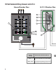
240 Volt Residential Wiring Schematic with G.F.C.I. G.F.C.
Spa System Box 240VAC Service Bottom view of G.F.C.I CLASS G FUSE 30A K6 F5 J73 G C WHT AC J11 J25 J63 J15 J23 W1 NEUTRAL WHITE NEUTRAL WHITE 120/240VAC 16/40A MAX 60Hz HOT BLACK HOT BLACK TORQUE RANGE FOR TB1: 27-30 IN. LBS. HOT RED HOT RED USE ONLY COPPER CONDUCTORS: #6 AWG MIN. Black (Hot) 7 K4 F4 FUSE .3A 250V 2 K3 K2 TB1 White White 3 1 J32 J33 F2 RED AC Red (Hot) Balboa 6 HTR2 HTR1 4 NEUTRAL WHITE HOT BLACK HOT BLACK HOT RED HOT RED C G C E.
Wiring Checks SYSTEM BOX WIRE GAUGE CHECK WIRING CHECK PRECAUTIONS UÊ When working in a system box always be aware that it may contain high voltage. UÊ Always keep your fingers and hand tools away from any wiring or circuit board when the power is on. Touching anything in these areas can result in serious injury. UÊ All service calls, no matter how minor, should include a complete wiring check, beginning with the house breaker.
Spa Behavior -- Start-up Information See manufacturer’s owners manual or reference card for general information on operating the spa, including programming filters and other settings that are changed from the topside control panel. PRIMING MODE HEATER START UP INFORMATION In Priming Mode, the “Mode” button toggles the ozone on/off (with a 15-second time-out). This can be useful if you want to verify ozone generator operation without waiting for a filter cycle.
Diagnosing M7 Topside Control Panels Panel messages are a quick clue toward solving a variety of problems. Here are the most common messages and what they mean. PRELIMINARY PANEL CHECK UÊ If the problem is not obvious, look on the topside control panel for diagnostic messages. If no messages are seen, run through all spa functions and note any inconsistent operation. UÊ Most error messages are stored in the fault log. To view the fault log, the spa must be in test mode and the spa light must be turned on.
NOTE: A common programming mistake is overlapping filter times that may cause the spa to filter continuously. UÊ Check the water level. UÊ Check the water temperature with an accurate temperature thermometer. Remove the spa cover and allow the water to cool to below 108° F. Adding cool water may be necessary. Touch any button to reset the system. If the water is still hotter than the set temperature, press the blower button (if applicable) to cool the spa. If the Problem Recurs, test the Sensor Set.
Diagnosing M7 Topside Control Panels (cont.) NOTE: This auxiliary freeze protection functions at all times, even when another fault condition has occurred and has otherwise shut the spa down. Any time the lower of the two temperature sensors goes below 45°F, all pumps/blowers turn on. They continue to run for 4 minutes after the temperature reaches 45°F or above. As soon as the temperature falls below 45°F again, this process restarts.
LOW VOLTAGE At Balboa, it’s been our experience that the majority of the problems associated with electronic control systems are due to low voltage. BROWN OUTS “Brown outs” can have an effect on the spa’s operation in a variety of ways. The control panel may go blank, have scrambled messages on the LCD, or only a few features will function. If the system is getting the proper voltage at TB1, but still doesn’t operate, then test for a blown power input fuse.
Diagnosing M7 Topside Control Panels (cont.) UÊ NOTE FOR ALL SYSTEMS In each situation, the most likely reason for the system power input fuse to blow is a pump problem. However, on occasion, a blower problem may also cause this fuse to blow if a 10A blower fuse is not built in. Once the power input fuse has been changed UÊ Probe the red wire and the white neutral wire. Again, voltage must be between 108 and 132 V. UÊ Check the voltage between the black and red wires again.
ML Series Panels -- For Use with EL and GL Systems ML900 Time Warm Jets 1 Jets 2 Jets 3 Option Mode/Prog Cool Invert Fiber Light Blower F1 F2 PL TL Warm Light Blower Mode/Prog Cool Jets 1 Jets 2 F2 PL TL “Molex” Type, ML/GL Connector ML553 ML554 ML700 Time F1 Light Warm ML551 Mode Heat Jets 2 Cool Blower Heat Cool ML200 ML240 Warm Jets 1 Jets 2 Blower Light Mode Heat Jets Aux Temp ML260 ML400 ML550 Jets 1 Jets Jets Jets Aux Light Aux Temp Light Aux Te
ML900 Panel Operation Diagnostic Messages section for the ML900 is unique. Refer to the User Guide for additional information. User Guide for panel ML900 is 40568-99. Initial Start-up Locking the Panel When your spa is first actuated, it will go into Priming mode (after displaying some configuration information). Please see “Spa Behavior -- Start-up Information” for additional information. Press “Time” “Jets 1” then “Warm” within 3 seconds. When locked, the PL “ PL ” light will light.
ML700 Panel Operation Diagnostic Messages section for the ML700 is unique. Refer to the User Guide for additional information. User Guide for panel ML700 is 40520-99. Initial Start-up other button to exit. When your spa is first actuated, it will go into Priming mode (after displaying some configuration information). Please see “Spa Behavior -- Start-up Information” for additional information.
ML550, 551, 554 Panel Operation Please refer to the following User Guides for more detailed information: ML551/ML554 User Guide: P/N 40632-99 ML 550 User Guide: P/N 40569-99 Light Mode Warm Light Warm Mode Heat Jets 1 Jets 2 Blower Heat Jets 1 Cool Jets 2 Cool Blower ML551 ML554 Heat Cool Warm Jets 1 Jets 2 Blower Light Mode ML550 Cool/Warm ML500, 551, 554 Jets 1 Press the “Cool” or “Warm” button once to display the set temperature.
NOTE: If your system does not have a “Blower” button, and is labeled as ”Jets 3” instead, please refer to the respective User Guide listed above. Light Some systems are equipped with both a spa light and a fiber optic light; however, only one can be accessed by this panel. (Larger panels may be purchased so that both the spa light and fiber optic light can be utilized.
ML550, 551, 554 Panel Operation (cont.) Circ Pump (optional) User Preferences If your system is equipped with a circ pump, it may be configured to work in one of three different ways: 1) The circ pump operates continuously (24 hours) with the exception of turning off for 30 minutes at a time when the water temperature reaches 3°F (1.5°C) above the set temperature (most likely to happen in very hot climates). 2) The circ pump stays on continuously, regardless of water temperature.
Editing User Preferences View the setting. The left two characters (before the decimal point) tell you what setting you’re viewing or editing, the right most character (after the decimal point) tells you the value of that setting (for example, “ ” for Yes or “ ” for No). If the value is flashing, you’re editing it. If the value is not flashing, you’re just viewing it. Press “Jets 1” to switch editing of the value on (flashing) or off (not flashing).
ML200, 240, 260, 400 Panel Operation Please refer to the following User Guides for more detailed information: ML400 User Guide: P/N 40570-99 ML260 User Guide: P/N 40633-99 ML240 User Guide: P/N 40634-99 ML200 User Guide: P/N 40571-99 Heat Jets Jets Aux Temp Aux Temp Light Light ML400 The pump responsible for heating and filtration (pump 1 low on non-circ systems, or the circ pump on circ systems) will be referred to simply as the pump.
Sleep mode heats the spa to within 20°F (11°C) of the set temperature only during filter cycles. “ ” will appear on the display until mode is changed. Standby Mode ML400 Pressing “Temp” followed by “Aux” or “Jets 2” or “Blower” will turn off all spa functions temporarily. This is helpful when changing a filter. Pressing any button exits Standby mode. On some systems the “Jets” button will control the pump in Standby Mode (“Drain Mode”). In this case, press any other button to exit.
ML200, 240, 260, 400 Panel Operation (cont.) Clean-up Cycle (optional ML400) When a pump or blower is turned on by a button press, a clean-up cycle begins 30 minutes after the pump or blower is turned off or times out. The pump and the ozone generator will run for one to four hours, depending on the system. (On some systems, you can change this setting; see User Preferences section.
– Temperature in Celsius ”, temperatures are displayed When set to “ on the panel in degrees Celsius. When set to “ ”, temperatures are displayed in Fahrenheit. – 24-hour Time Display ”, time is displayed in 24-hour When set to “ (military) format (00:00 is midnight, 23:00 is one hour before midnight). When set to “ ”, time is displayed in 12-hour (am/pm) format (12:00 is midnight, 11:00 pm is one hour before midnight). – Clean-up Cycle Duration (some systems only) ”, Clean-up Cycles are disabled.
VL Series Panels -- For use with VS and GS Systems Warm Blower Light Mode / Prog Cool Jets 1 Jets 2 Time Warm Blower Light Mode/Prog Cool Jets 1 Jets 2 Mode Warm VL702S Blower Heat Jets 1 VL701S Blower Jets 2 Light Mode Cool Warm Heat Jets 2 Light Cool VL600S VL700S Jets 1 32 DELUXE SYSTEMS Time Jets Warm Mode Blower Light Jets Blower Light Heat Cool STANDARD SYSTEMS VL801D VL802D p “Phone Plug” RJ Type, VL/VS Connector
VL406U VL406T Jets Warm Light Cool Heat Jets Temp Blower Light Heat “Phone Plug” RJ Type, VL/VS Connector Set Heat VL403 Jets Light Note: VL404 and VL403 have red LED’s on black background Heat Blower Jets Temp Light VL402 Blower Heat Jets Heat Blower Jets Temp Light Set VL200 VL240 VL260 VL400 VL401 Light DUPLEX SYSTEMS VL404 Blower Blower Jets Blower Jets Temp Light Temp Light 33
VS/GS Panel -- 300 & 500 Series and Operation Please refer to the User Guides for additional information.
On panels with “Warm” and “Cool” buttons, to display the set temperature, press “Warm” or “Cool” once. To change the set temperature, press a temperature button again before the display stops flashing. Each press of “Warm” or “Cool” will adjust the set temperature. After three seconds, the display will stop flashing and begin to display the current spa temperature. JETS Jets 1 500Z, 500DZ, 500SZ Series Press “Jets 1” to turn pump 1 on or off, and to shift between low and high speeds (if equipped).
VS/GS Panel -- 300 & 500 Series and Operation (cont.) Mode/Prog 500DZ UÊ Mode is changed by pressing “Warm” or “Cool,” then pressing “Mode/Prog” button. UÊ Standard Mode maintains set temperature and the STANDARD icon will be displayed. UÊ ECONOMY Mode heats the spa to the set temperature will display when water only during filter cycles. temp is not current, and will alternate with water temp when the pump is running. The ECONOMY icon will be displayed.
Preset Filter Cycles 300, 300F (Software v. 38) UÊ The first preset filter cycle begins 6 minutes after the spa is energized. The second preset filter cycle begins 12 hours later. UÊ For 300-series systems, filter duration is programmable for 2, 4, 6, or 8 hours or for continuous filtration (indicated by ). The default filter time is 2 hours. UÊ For 300F-series systems, filter duration is programmable for 1, 2, 3, 4, 5, 6, 7, or 8 hours or for continuous filtration (indicated by ). The default filter time is 1 hour.
EL and GL Series Mach 3 -- Persistent Memory & Power Up This document applies when using ML Series panels with any EL or GL Mach 3 series system.
VS-GS Persistent Memory with VL Panels Any time you change a DIP Switch, other than A1, you must reset Persistent Memory for your new DIP Switch Settings changes to take effect. If you do not reset Persistent Memory, your system may function improperly. To reset Persistent Memory: s Power down by disconnecting power source from spa. s Put a jumper across J43, covering both pins. (See illustration below) s Power up by connecting power source to spa. s Wait until “ ” is displayed on your panel.
Testing the Circuit Board Output BALBOA’S QUICK TESTTM TEST KIT TO USE THE BALBOA QUICK CHECK If your topside control panel is working properly, but a pump, blower, or other device does not activate when its panel button is pressed, further diagnosis is easily accomplished with the Balboa Quick Check, which is designed to test output voltage on a variety of Balboa systems. The following system outputs can be tested using the Balboa Quick Check: UÊ Turn off the power at the house breaker box.
Testing the Sensor Set 1. Check sensor wires for cracks or damage that may indicate the presence of a rodent. 2. Inspect the connections of both sensors on the circuit board. The plugs must be clean. 3. If the sensors are not totally failing but are showing excessive (2° F/1.
Changing a System Circuit Board HOW TO REPLACE A SYSTEM CIRCUIT BOARD Important! Be sure to turn the power off before replacing any component, especially a circuit board. Important! DO NOT REMOVE AND REPLACE THE CIRCUIT BOARD UNLESS THE FAULT HAS POSITIVELY BEEN DETERMINED TO BE THE CIRCUIT BOARD. HOW TO REMOVE A SYSTEM CIRCUIT BOARD NOTE: Before you begin, labeling all wires to be removed may help speed up reinstallation. The wiring diagram should always be used to ensure proper wire placement.
Removing the Heater Assembly from a Spa System Note: Be careful when removing a heater assembly from a spa plumbing system. Water may splash out under pressure. Water under pressure in the plumbing may splash out, and onto the system’s electronic board. Do not remove the system door until the water has been drained from the heater assembly housed in the system. 1. Turn off the main power. 2. Close off the slice valves (or, ball valves) adjacent to the heater assembly. 3.
Panel Message Reference Guide Message Meaning / Frequency 5FNQFSBUVSF OPU DVSSFOU JO &DPOPNZ PS 4MFFQ NPEF *O &DPOPNZ PS 4MFFQ NPEF UIF QVNQ NBZ CF PGG GPS IPVST PVUTJEF B mMUFS DZDMF *G ZPV XJTI UP TFF UIF DVSSFOU TQB UFNQFSBUVSF FJUIFS TXJUDI UP 4UBOEBSE NPEF PS UVSO +FUT PO GPS NJOVUFT 1MFBTF TFF i%JBHOPTJOH 5PQTJEF $POUSPM 1BOFMTw 1BHF $POmHVSBUJPO FSSPS 4QB DBOOPU TUBSU VQ 1MFBTF TFF i%JBHOPTJOH 5PQTJEF $POUSPM 1BOFMTw 1BHF "T OFFEFE < > *OTUBMM OFX .
5IF QVNQ JT PO EVSJOH 4UBOECZ .PEF UP BTTJTU JO ESBJOJOH UIF TQB 1SFTT i+FUT w UP UVSO PGG UIF QVNQ XIFO XBUFS IBT ESBJOFE PS QPXFS PGG UIF TQB *OBEFRVBUF XBUFS EFUFDUFE JO IFBUFS %JTQMBZT PO UIJSE PDDVSSFODF PG iESw NFTTBHF 4QB JT TIVU EPXO < > 'PMMPX BDUJPO SFRVJSFE GPS NFTTBHF 4QB XJMM OPU BVUPNBUJDBMMZ SFTFU 1SFTT BOZ CVUUPO UP SFTFU NBOVBMMZ 5IF TQB JT PQFSBUJOH JO &DPOPNZ .
Panel Message Reference Guide (cont.
&WFSZ EBZT < > $MFBO DPOEJUJPO DPWFS QFS NBOVGBDUVSFS T JOTUSVDUJPOT Reminder, Suppress in User Preferences. [2] &WFSZ EBZT < > %SBJO BOE SFmMM TQB QFS NBOVGBDUVSFS T JOTUSVDUJPOT Reminder, Suppress in User Preferences. [2] &WFSZ EBZT < > 5FTU BOE BEKVTU Q) DIFNJDBM MFWFMT QFS NBOVG JOTUSVDUJPOT Reminder, Suppress in User Preferences. [2] &WFSZ EBZT < > 5FTU BOE BEKVTU TBOJUJ[FS DIFNJDBM MFWFMT QFS NBOVGBDUVSFS T JOTUSVDUJPOT Reminder, Suppress in User Preferences.
Panel Message Reference Guide (cont.) 4QB JT TIVU EPXO < > 5IF TFOTPS UIBU JT QMVHHFE JOUP UIF 4FOTPS i#w KBDL JT OPU XPSLJOH 5FTU TFOTPS BOE SFQMBDF JG CBE 1MFBTF TFF 5FTUJOH UIF 4FOTPS 4FU 1BHF 4FOTPST BSF PVU PG CBMBODF *G UIJT JT BMUFSOBUJOH XJUI UIF UFNQFSBUVSF JU NBZ KVTU CF B UFNQPSBSZ DPOEJUJPO *G UIF EJTQMBZ TIPXT POMZ UIJT NFTTBHF QFSJPEJDBMMZ CMJOLJOH UIF TQB JT TIVU EPXO < > 5FTU TFOTPS BOE SFQMBDF JG CBE 1MFBTF TFF 5FTUJOH UIF 4FOTPS 4FU 1BHF 4MFFQ .