
Owner's manual


1
APPLICATION GUIDELINES FOR THE
BALBOA M-7 CONTROL SYSTEM
he Balboa M-7 control is a revolutionary control system that provides additional reliability and ease of installation when compared to
conventional spa control systems. The software-based M-7 control system makes decisions based upon temperature and flow conditions that
exist within the heater. The system operates properly if there is a minimum of 20 gpm flowing through the heater under all hydraulic variables
and at worst case conditions. This not only assures proper control operation, but also increases heater life. The goal for the spa design-
er is to design a circulation system that, when used with the proper pump, will provide a uniform flow in either direction
through the heater. This uniform flow must occur during heating and filtering cycles and must not fall below 20 gpm under
any circumstances.
These guidelines are intended to help you design your spa to achieve this goal so that you can take advantage of the new Balboa M-7 control
system. Please read these guidelines carefully and study the plumbing schematics before attempting to test the system or
install it in a spa.
Basic Spa Configurations Supported By The M-7 Control System
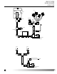
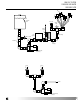
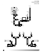
1. Non-circ system
(System that uses a 2-speed pump to heat and filter the spa.)
A. Vacuum side heater.
(A heater that is located on the suction side of the pump.)
B. Pressure side heater.
(A heater that is located on the discharge side of the pump.)
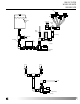
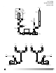
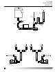
2. Circ system
(System that uses a dedicated 1-speed pump to heat and filter the spa. The pump motor must not exceed 2amp.)
NOTE: The amperage limitation for the Circ Pump must be adhered to so as not to overload the printed circuit board ampacity.
A. Vacuum side heater.
(A heater that is located on the suction side of the pump.)
B. Pressure side heater.
(A heater that is located on the discharge side of the pump.)
T