Linear Motors Installation & Operating Manual 1/01 MN1800
Table of Contents Section 1 General Information . . . . . . . . . . . . . . . . . . . . . . . . . . . . . . . . . . . . . . . . . . . . . . . . . . . . . . . . . . . . . . . . . . . . . . . . . . . . . . . 1-1 Overview . . . . . . . . . . . . . . . . . . . . . . . . . . . . . . . . . . . . . . . . . . . . . . . . . . . . . . . . . . . . . . . . . . . . . . . . . . . . . . . . . . . . . 1-1 Limited Warranty . . . . . . . . . . . . . . . . . . . . . . . . . . . . . . . . . . . . . . . . . . . . . . . . .
Bearing Maintenance . . . . . . . . . . . . . . . . . . . . . . . . . . . . . . . . . . . . . . . . . . . . . . . . . . . . . . . . . . . . . . . . . . . . . . . . . . . 2-31 Recirculating Bearing Rail And Block . . . . . . . . . . . . . . . . . . . . . . . . . . . . . . . . . . . . . . . . . . . . . . . . . . . . . . . . . 2-31 Cross Roller Type Bearing . . . . . . . . . . . . . . . . . . . . . . . . . . . . . . . . . . . . . . . . . . . . . . . . . . . . . . . . . . . . . . . . . .
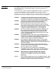
Section 1 General Information Overview This manual contains general procedures that apply to Baldor Linear Motor products. Be sure to read and understand the Safety Notice statements in this manual. For your protection, do not install, operate or attempt to perform maintenance procedures until you understand the Warning and Caution statements. A Warning statement indicates a condition that can cause harm to personnel. A Caution statement indicates a condition that can cause damage to equipment.
Safety Notice: This equipment contains high voltage! Electrical shock can cause serious or fatal injury. Only qualified personnel should attempt installation, operation and maintenance of electrical equipment. Be sure that you are completely familiar with NEMA publication MG-2, safety standards for construction and guide for selection, installation and use of electric motors and generators, the National Electrical Code and local codes and practices.
Receiving Each Baldor motor is thoroughly tested at the factory and carefully packaged for shipment. When you receive your motor, there are several things you should do immediately. 1. Observe the condition of the shipping container and report any damage immediately to the commercial carrier that delivered your motor. 2. Verify that the part number of the motor you received is the same as the part number listed on your purchase order.
1-4 General Information MN1800
Section 2 Installation & Operation Overview Installation should conform to the National Electrical Code as well as local codes and practices. When other devices are coupled to the motor, be sure to install protective devices to prevent accidents. Machinery that is accessible to personnel should provide protection in the form of guard rails, screening, warning signs etc.
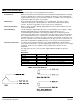
LMAC Linear Induction Motor General Description: Single or three phase, linear AC induction motor primary. Construction: Epoxy encapsulated and steel laminated coil assembly (motor primary) Motor secondary (customer supplied) must conform to the following specifications: 1/8–inch aluminum or copper plate backed by a 1/4 inch cold rolled steel plate. The width of the secondary must be at least the with of the motor coil assembly.
LMBR Series Brush DC Linear Servo Motor Mounting The motor primary must be aligned (parallel) to the equipment guide ways within 0.005″ (0.127mm) on each end. Use gauge blocks and shims as necessary. Precise parallel alignment of the motor to the equipment guideways is required. Align the stationary half of the motor to the guideways. Then align the moving half with the stationary half. When securing the primary to the equipment base do not allow the screws to penetrate the motor more than .
LMBL Series Brushless Linear Iron Core Servo Motor Installation Refer to Figure 2-1. 1. Install the magnet assembly onto the machine mounting base. 2. With the slide assembly removed from the rails, install the coil assembly onto the slide, tightening the mounting screws. 3. Place a non–magnetic shim over the magnets, sized to cover all the magnets. (The shim thickness must be equivalent to the air gap specification. The normal air gap is 0.030″ ± 0.005″ unless otherwise specified). 4.
LMBL Series Continued Brushless Linear Iron Core Servo Motor Continued Multiple Coil Assembly Operation In addition to maintaining an air gap, multiple coil assemblies must also maintain a spacing factor of 1.8″. In other words, the space between coil assemblies may vary, however, the distance from the front end of the first coil assembly to the front end of the next must be a multiple of 1.8″. See Figure 2-2. Ensure that this spacing is established at the time of installation.
LMBL Series Continued Brushless Linear Iron Core Servo Motor Modular Magnet Track Installation Continued Refer to Figure 2-3. Some magnets are provided in modular segments. This is the recommended procedure to install these modular magnet track sections. Note: It is recommended that rubber coated tool handles be used to reduce injury (pinching fingers etc.) and protect the surface of the magnets. 1. 2. Bolt the coil assembly onto the underside of the slide (carriage).
LMBL Series Continued Brushless Linear Iron Core Servo Motor Modular Magnet Track Continued Continued 4. Install the remaining magnet track sections on the base plate. See Figure 2-5. 5. Remove the air–gap setting shim from the magnet track before use. Figure 2-5 Modular Magnet Track Installation Install other section of magnet track with slide positioned as shown Guide Rail Operation Considerations The motor must always be operated within the specified operating parameter limits.
LMCF Series Brushless Linear Cog Free Servo Motor 1. Install the coil and magnet assemblies. While mounting the coil, be sure to adjust coil assembly so it is centered within the magnet assembly with equal air gap in the vertical and horizontal positions. See Figure 2-6. 2. Verify that the coil assembly is centered within the magnet assembly with equal air gap in the vertical and horizontal positions along its entire length of travel.
LMCF Series Brushless Linear Cog Free Servo Motor Continued LD9073A00 Hall Sensor Cable Connections (6 pin to flying leads) Pin# 1 2 3 4 5 6 Color Black Red Green White Brown Description C B N.C. Ground A +5VDC LMNC Moving Coil Type General Description Bi–directional DC linear motor consisting of a moving wound bobbin assembly and a stationary magnet assembly. (Refer to catalog BR1800 for motor specifications, if your motor is custom; refer to documentation included with shipment or contact Baldor).
LMNM Moving Magnet Type Non Commutated DC Linear Servo Motor General Description: Bi–directional DC linear motor with integral bearing. (Refer to catalog BR1 800 for motor specifications, if your motor is custom; refer to documentation included with shipment or contact Baldor) Construction: Anodized aluminum or plated steel housing, aluminum end–caps, steel center shaft.
LMPY Series Polynoid Linear Motor Holding Option Mounting: Switching: The rectifier package is wired externally in the stator circuit. For 115/60Hz, rectifier package CO0126A00 is provided. For 230/60Hz, rectifier package CO0125A00 is provided. Rated holding force is only achieved when the keeper plate is against the holding coil. To reduce shock loads, a shock absorbing connection between the polynoid rod and the load is recommended. Two switching modes can be used for various applications.
LMPY Series Continued Polynoid Linear Motor Holding Option Continued Operation Considerations The motor must always be operated within the specified operating parameter limits. Exceeding those limits will permanently damage the motor. Note: Rod should not support axial loads that can induce premature bearing failure. The following steps must be completed to ensure safe and proper operation. 1. Verify that all electrical wiring and cables are properly connected.
LMSS Series Linear Stepper Roller Bearing Motor Installation Prior to placing the Forcer on the Platen both surfaces must be cleaned. Use this method: 1. Apply masking tape to lamination surface of the Forcer to remove any metallic contaminants. 2. Using alcohol, clean both surfaces to remove any adhesive residue and any other contaminants on the Forcer and the Platen. Note: Apply small amount of alcohol to cloth for cleaning.
LMSS Series Continued Air Bearing Motor Cleaning the Forcer and Platen Prior to placing the Forcer on the Platen both surfaces must be cleaned. Use this method: 1. Apply masking tape to lamination surface of the Forcer. Removing the tape removes large particle contaminants. 2. Using alcohol, clean both surfaces to remove any adhesive residue and any other contaminants on the Forcer and the Platen. Note: Apply small amount of alcohol to cloth for cleaning.
LMDS Series Dual Axis Linear Stepper Motor Items Required but NOT Included 1. A regulated 80 PSI air supply with a 5 micron filter for each motor. A water separator is also required. 2. Two or four phase, 2 ampere (micro) stepper motor driver/controller for each motor. Cleaning the Forcer and Platen Prior to placing the Forcer on the Platen both surfaces must be cleaned. Use this method: 1. Apply masking tape to lamination surface of the Forcer. Removing the tape removes large particle contaminants. 2.
Leadwire Connection LD9068A00 Color Pin# Red 1 Green 2 Yellow 3 Orange 4 Black 5 Blue 6 Green 7 White 8 Black 9 Description (2 Phase 9 pin to flying leads) (X) A+ Winding (X) A– Winding (X) B+ Winding (X) B– Winding Ground (Y) A+ Winding (Y) A– Winding (Y) B+ Winding (Y) B– Winding 6 7 8 9 1 2 3 4 5 Female (D Sub) 1 2 3 4 5 6 7 8 9 10 11 12 13 14 15 LD9074A00 Color Pin# Description (2 Phase 25 pin pin to flying leads) 16 17 Red 1 (X) A+ Winding 18 Green 2 (X) A– Winding 19 Yellow 3 (X) B+ Winding 20 O
LSE Series Enclosed Position Stage General Description: Single axis linear stage with linear motor, linear bearings, linear encoder, limit switches, cable carrier, and bellows Construction: Hard anodized aluminum Bearing type: Recirculating ball linear bearing Encoder type: Open glass scale, optical, magnetic Motor type: Brushless three phase, iron core or cog free type linear motor. Refer to catalog for motor specifications and stage model number description.
AY1775A00 LSE, Encoder (RGH24) & Hall Connections for LinDrive/MintDrive (15 pin to flying leads) Color Green Blue Pink White Yellow Red Gray Black Red Brown White Pin# 1 2 3 4 5 6 7 8 9 10 11 12 13 14 15 Description A+ B+ C+ Hall1 N/C A– B– C– Hall3 Hall2 +5VDC (Halls Brown) N/C Encoder GND (Halls Green) 11 12 13 14 15 1 2 3 4 5 Male (D Sub) Outer shield to shell. Inner shield to pin 13. AY1779A00 LSE with Renishaw Encoder (RGH24) Flying Leads 10 ft cable for use with Renishaw RGH24.
Internal Connections Leadwire Connection Limit Switch Pigtails Limit 4 Description Limit & Home power * N/C Limit Output Ground OUT 671P LD9125A01 Limit only Color Pin# Brown 1 2 White 3 Green 4 3 L 2 * Limit & Home power is +4 to +24VDC. 1 H–Limit LD9125A02 Limit and Home Description Limit & Home power * Home Output Limit Output Ground Home 4 OUT L OUT 671P Pin# 1 2 3 4 671P Color Brown Black Red Green 3 L 2 * Limit & Home power is +4 to +24VDC.
2-20 Installation & Operation LD9124A00 LD9123A00 LD9125A02 LD9125A01 Limit Home Limit LSE Stage Connector Locations MN1800
LSC Series Cross Roller Position Stage General Description: Single axis linear stage with linear motor, linear bearings, linear encoder, limit switches, cable carrier (on some models), and bellows Construction: Hard anodized aluminum, black oxide steel Bearing type: Cross roller linear bearing Encoder type: Open glass scale if internal, or enclosed type if external Motor type: Brushless three phase, iron core or cog free type linear motor.
AY1775A00 Leadwire Connection for LinDrive 15 pin Color Green Blue Pink White Yellow Red Gray Black Red Brown White Pin# 1 2 3 4 5 6 7 8 9 10 11 12 13 Description A+ B+ C+ Hall1 N/C A– B– C– Hall3 Hall2 +5VDC N/C Encoder GND (Halls Brown) 11 12 13 14 15 1 2 3 4 5 Male (D Sub) Outer shield to shell. Inner shield to pin 13. 14 15 AY1779A00 LSE with Renishaw Encoder (RGH24) Flying Leads 10 ft cable for use with Renishaw RGH24. Flying leads are color coded as shown in this diagram.
Leadwire Connection Limit Switch Pigtails Limit 4 Description Limit & Home power * N/C Limit Output Ground OUT 671P LD9125A01 Limit only Color Pin# Brown 1 2 White 3 Green 4 3 L 2 * Limit & Home power is +4 to +24VDC. H–Limit Home 4 OUT OUT 671P L 671P LD9125A02 H–Limit and Home Color Pin# Description Brown 1 Limit & Home power * Black 2 Home Output Red 3 Limit Output Green 4 Ground 1 3 L 2 * Limit & Home power is +4 to +24VDC.
LSS Series Single Bearing Position Stage General Description: Single axis linear stage with cog–free linear motor, linear bearings, optical linear encoder, limit switches, cable carrier and bellows Construction: Magnet assembly/stage base is hard chrome plated steel. Slide is hard anodized aluminum Bearing type: Recirculating ball type linear bearing Encoder type: Open scale optical Motor type: Brushless, three phase, cog free type linear motor.
AY1801A00 Stages with Renishaw Encoder (RGH22) Flying Leads 10 ft cable for use with Renishaw RGH24. Flying leads are color coded as shown in this diagram. Cable 1 (Hall Cable) Cable 2 (Motor Cable) Cable 4 (RGH22 Encoder Cable) Cable 3 Limit Cable (optional) * Limit & Home power is +4 to +24VDC.
LSX Series Single Bearing Position Stage General Description: Single axis linear stage with linear motor, linear bearings, magnetic encoder, limit switches, cable carrier and bellows Construction: Hard anodized aluminum Bearing type: Recirculating ball type linear bearing Encoder type: Magnetic Motor type: Brushless three phase, iron core linear motor. Refer to catalog for motor specifications and stage model number description.
AY1682A00 LSX Stage Endplate Internal Connections Motor / Limit Connections 19 Pin Circular Connector (Male) 19 Pin Circular Connector (Male) A M C N L U J P D V K T H Encoder / Hall Connections 15 Pin D Sub (Male) B R E S F G 15 Pin D Sub (Male) 11 12 13 14 15 1 2 3 4 5 Male (D Sub) Color Green Pink Brown White Yellow Red Gray Black Red White Pin# 1 2 3 4 5 6 7 8 9 10 11 Black 12 13 14 15 MN1800 Description A+ B+ C+ Hall1 N/C A– B– C– Hall3 Hall2 +5VDC (Halls Brown) N/C Encoder GND (Ha
LD9102A00 LSX Motor/Limit Cable Connections (19 pin to flying leads) 19 Pin Circular Connector (Female) A M U C P D V K J B N L R T E S Blue Orange F H 19 Pin Circular Connector (Female) Color Red White Black Green G Note: Motor phasing is for LinDrive or MintDrive. Other controls may require different phasing (such as most trap drives (U) Black, (V) Red, (W) White). Phase angle between phases is 120 degrees.
LSX Leadwire Connection Limit Switch Pigtails White Green Limit Pin# 1 2 3 4 4 Description Limit & Home power * N/C Limit Output Ground OUT 670P LD9119A01 Color Brown 3 L 2 1 * Limit & Home power is +4 to +24VDC. Limit 670P OUT LD9119A02 Color Brown Black Red Green L Pin# 1 2 3 4 Description Limit & Home power * Home Output Limit Output Ground 4 3 Home 2 670P OUT * Limit & Home power is +4 to +24VDC.
AY1743A00 LSX Internal Encoder/Hall Cable (15 pin to 8 pin and 6 pin) Color Green Blue Pink White Yellow Red Gray Black Red Brown White Pin# 1 2 3 4 5 6 7 8 9 10 11 12 13 14 15 Description A+ B+ C+ Hall1 N/C A– B– C– Hall3 Hall2 +5VDC N/C Encoder GND (Halls Brown) Hall Shield Encoder Shield 8 Pin Encoder Connector Hall Cable LD9073A00 11 12 13 14 15 1 1 2 3 4 5 4 6 8 7 2 5 3 Male (D Sub) 8 Pin Encoder Connections Outer shield to shell. Inner shield to pin 13.
Bearing Maintenance Recirculating Bearing Rail And Block Lubrication type: For grease lubrication, a lithium–soap base grease (consistency No. 2 of JIS) is most frequently used. For linear guides operating under a heavy load, a grease containing extreme pressure additive is recommended. Maintenance procedure: Clean rails with clean cloth. Apply a thin film of grease onto the rail.
Encoder Maintenance RSF Series MSA6x Enclosed Type Technical Data: Linear encoders measure the position of linear axis without mechanical translation components. This reduces the potential error due to thermal behavior of the linear motor and backlash from mechanical translation. Encoder type: Non contact optical, sealed type.
RSF Series MS6x Open Type Glass Scale Encoder type: Non contact optical, glass scale, open type. Open scale linear encoders are used primarily where environmental conditions are clean, dry and free of oils. Due to the fragile nature of the encoder scale, extra care should be taken to prevent physical damage from impact or abrasion. Mechanical design: Glass scale, optical scanning unit, high flex twisted shielded cable. Encoder is adhered to stage surface with a two part, releasable bonding agent.
Renishaw RGH22 series Open Type Metal Scale Encoder type: Non contact optical, metal scale, open type. Open scale linear encoders are used primarily where environmental conditions are clean, dry and free of oils. Due to the fragile nature of the encoder scale, extra care should be taken to prevent physical damage from impact or abrasion. Mechanical design: Metal scale, optical scanning unit, high flex twisted shielded cable. Encoder is adhered to stage surface with a two part, releasable bonding agent.
Renishaw RGH22 series Open Type Metal Scale Continued Specifications: DC Power: 5VDC @ 120mA Output Signal: Square wave differential line driver to EIA RS422 (except limit switch Q and external set–up signal X). Model RGH22D – RGH22X – RGH22Z – RGH22Y – Resolution 5µm resolution 1µm resolution 0.5µm resolution 0.1µm resolution Speed (m per second) 5 3 1.5 0.3 Edge Separation (µ seconds) 0.5 0.15 0.15 0.1 The non–contact optical encoder is designed for position feedback solutions.
ELGO Mix 4 series Magnetic Type Encoder type: Non contact, magnetic, open type. Open scale linear encoders are used primarily where environmental conditions are clean, dry and free of oils. The magnetic encoder scale is susceptible to damage from magnetic fields. Great care should be taken to isolate the magnetic scale from magnets, static electricity, and electrical current. Mechanical design: Magnetic scale with stainless steel protective cover, magnetic sensor unit, high flex twisted shielded cable.
Mix 4 and Mix 5 Dial Settings Dial Setting Resolution (using 4x multiplier) 1000 1000 µm/pulse (1mm) 500 µm/pulse 100 µm/pulse 50 µm/pulse 10 µm/pulse 5 µm/pulse 500 100 50 10 5 Note: These resolutions are only available with 4 edge counting mode. (0.5mm) (0.1mm) (0.05mm) (0.01mm) (0.005mm) ELGO Mix 5 series Magnetic Type Encoder type: Non contact, magnetic, open type. Open scale linear encoders are used primarily where environmental conditions are clean, dry and free of oils.
Encoder Head Output Connector Pin Assignment ML6040A00 Cable Color Black White Green Pink Brown Yellow Red Gray 1 4 6 8 2 7 5 3 Pin# 1 2 3 4 5 6 7 8 Description Encoder GND +5VDC Encoder A+ Encoder B+ Encoder C+ Encoder A– Encoder B– Encoder C– Encoder Specifications Encoder Model EMIX3 MIX4 MIX5 MS 61–46 (RSF) MS 61–36 (RSF) MS 61–26 (RSF) MS 62–27 (RSF) MS 63–55 (RSF) RGH24D (Renishaw) RGH24X (Renishaw) RGH24Z (Renishaw) RGH24Y (Renishaw) LR050RD (Danaher) LR025RD (Danaher) LR010RD (Danaher) Reso
Cables and Cable Chain Procedures If your positioning stage is supplied with a cable chain, follow these recommendations regarding its use: S Your stage is supplied with high flex cables that are designed to withstand millions of bend cycles. In addition, the internal conductors of the cable are twisted and shielded. A twisted, shielded cable reduces the problems associated with EMI and EFI noise. Using other types of cable may cause difficultly during servo tune procedure.
Additional Cables LD9110A00 LinDrive External Encoder Output X7 Leadwire Connection (9 pin to flying leads) Color Green Pink Brown Black Yellow Red Gray Pin# 1 2 3 4 5 6 7 8 9 Description A+ B+ C+ N.C. DGND A– B– C– N.C. 1 2 3 4 5 6 7 8 9 Male (D Sub) LD9101A00 LinDrive to Positioner Leadwire Connection (9 pin to 9 pin) LinDrive Cable End Connections Color Green Pink Brown Black Yellow Red Gray Pin# 1 2 3 4 5 6 7 8 9 Description A+ B+ C+ N.C. DGND A– B– C– N.C.
BALDOR ELECTRIC COMPANY P.O. Box 2400 Ft.