
Electric Company Water Heater User Manual


Installation & Operation 2-3MN1800
LMBR Series Brush DC Linear Servo Motor
Mounting The motor primary must be aligned (parallel) to the equipment guide ways within 0.005″
(0.127mm) on each end. Use gauge blocks and shims as necessary. Precise parallel
alignment of the motor to the equipment guideways is required. Align the stationary half
of the motor to the guideways. Then align the moving half with the stationary half.
When securing the primary to the equipment base do not allow the screws to penetrate
the motor more than .25″ deep (to prevent damage to the motor windings).
To mount the motor secondary, slide the table over the secondary and align the mounting
holes. The secondary is to be secured to the moving table with screws after the proper
amount of shims are added to maintain an air gap of .015″ min. to .020″ max. (unless
otherwise specified) between the secondary and the primary. This is achieved by
ensuring that the plastic shim provided does not bind anywhere over the length of the
primary when moving the table top with secondary back and forth by hand.
The plastic shim between the primary and the secondary can now be removed. Be sure
that the secondary is centered and runs parallel to the commutator to within .005″ at each
end.
Electrical Check: With an ohmmeter across input terminals, verify that the resistance reading does not drop
to zero when the secondary / commutator assembly is moved over the entire length of the
stationary primary. If a zero reading is observed, inspect the connections between the
commutator brushes and the power input wires. In addition, inspect the connections
between the motor windings and the commutator bar.
Motor Removal: Insert the plastic shim between the primary and secondary to maintain the air gap. First,
disconnect the power input wires. Next, remove the screws between the secondary and
the moving table as this allows the secondary to sit on the primary. Then remove the
mounting screws between the primary and the base. Finally, the complete motor
assembly can be removed and placed on a level, flat surface.
Secondary Removal: If just the secondary must be removed,slide the table with the secondary attached, to one
end of the primary. Insert a .015″ minimum plastic shim between the secondary and the
primary to maintain the air gap. Remove the screws between the secondary and the
sliding table. Move the table out of the way and slide the secondary out using extreme
caution so as to not damage the brushes. If brushes are worn out, contact Northern
Magnetics for replacement.
Secondary Reinstallation: Place .015″ minimum plastic shim on primary face. Next place .015″ min fiberglass shims
on the brush assembly and completely depress the brushes into their holders. With the
brushes toward the commutator bars, slide the secondary onto the primary face (with the
shim in place). When the secondary is in place, gently remove the shim from between
the brushes and commutator bars.
Note: Ensure that the shim between commutator and brushes has rounded ends
and that they do not cut the leads to the commutator bars.
Refer to “Mounting” instructions to reinstall.
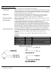
Brush Motor Connections: – Black / Red (+)
White (–)