
Electric Company Water Heater User Manual


2-2 Installation & Operation MN1800
LMAC Linear Induction Motor
General Description: Single or three phase, linear AC induction motor primary.
Construction: Epoxy encapsulated and steel laminated coil assembly (motor primary) Motor secondary
(customer supplied) must conform to the following specifications: 1/8–inch aluminum or
copper plate backed by a
1/4 inch cold rolled steel plate. The width of the secondary must
be at least the with of the motor coil assembly.
Maintenance: Motor should be kept dry and relatively free of contamination. This motor is water
resistant, not water proof. Avoid submersion. Avoid contact with petroleum–based
solvents. Alcohol or soapy water can be used to remove contaminants.
Motor specifications: Refer to catalog or outline drawing supplied with motor for mechanical dimensions and
electrical specifications.
Motor Mounting: Your motor may be supplied with either base or foot mounting, refer to catalog or outline
drawing supplied with motor for mounting details and hole dimensions. It is
recommended that all available coil assembly mounting holes be utilized to properly
secure the coil assembly. If the coil is in motion, the motor wires must be strain relieved.
We recommend that the motor secondary be secured with 1/4inch fasteners on the left
and right sides of the secondary, every four to six inches of its length. An air–gap of 1/8
inch is recommended. Refer to linear induction motor duty cycle–force–current curves in
this booklet for information regarding the affects of air–cap size on motor performance.
Electrical Connections For voltage and current specifications, refer to Catalog BR1800 or to documentation
enclosed for custom motors. The 10 foot flying leads can be cut to remove excess length
if required. Connectors are available; contact a Baldor representative for more
information.
For single phase motors, refer to the table supplied with this booklet for capacitor
selection.
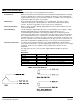
Motor Wire
Function Gauge Color
Phase A 10 Red
Phase B 10 Blue (substituted by black in older models)
Phase C 10 White
Ground Motor housing
Thermal switch 20 Orange (two wires, interchangeable)
Thermal warning 20 Black (two wires, interchangeable)
LMAC Connection Diagram