23456789012345678901234567890121234567890123456789012345678901212345678901234 123456789012345678901234567890121234567890123456789012345678901212345678901234 123456789012345678901234567890121234567890123456789012345678901212345678901234 123456789012345678901234567890121234567890123456789012345678901212345678901234 123456789012345678901234567890121234567890123456789012345678901212345678901234 123456789012345678901234567890121234567890123456789012345678901212345678901234 12345678901234567890123456789012123456
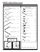
#89869 Add-On Floor Carrel Part Drawing Description Part Qty Drawing Description Qty Hardware List P-1 P-2 P-3 P-4 P-5 P-6 P-7 P-8 Middle Side Panel Top Panel Back Panel Keyboard Panel Middle Leg Left Keyboard Slide 1 EA A Socket Screw M5X15 mm 1 EA A1 Wood Screw #6X½ 12 EA A2 Wood Screw #8X2¼ 2 EA 1 EA 1 EA B Interior Threaded Post 1 EA B1 Washer 4 EA C Cam Lock 11 EA D Cam Post 11 EA E Wood Dowel 4 EA F Glide Bracket 1 EA G Glide 2 EA H Grommet Sleeve
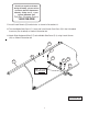
#89869 Add-on Floor Carrel Assembly Diagram To Assemble: Identify and Separate all the Parts and Hardware. 1. Remove Keyboard from #89830 Carrel as shown in illustration # 1a. Remove left leg Assembly from #89830 Carrel as shown in illustration # 1b. Illustration # 1a Illustration # 1b 2. Place the Middle Leg (P-5) with the three threaded holes facing up. Install 7 Cam Posts (D) in Leg as shown in illustration # 2. 3. Install 1 Leveling Glide (G) in the bottom of leg as shown in illustration # 2.
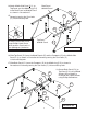
5. Place the Middle Side Panel (P-1) with the Camlocks(C) facing up and install 2 each Cam Posts (D) in the 2 threaded insert nuts (Pre-installed) as shown in illustration # 3. Phillips Screwdriver Be sure that arrow on top of Camlock (C) aligns with centerline of Edge Drilled hole. Arrow 6. Install 2 each Dowels (E) into the holes as shown in illustration # 3. 7. Attach Middle Side Panel (P-1) to Middle Leg (P-5 ) as shown in illustration # 3.
Should you require assistance during assembly, please call our Customer Service Department Monday - Friday 8 a.m. - 5 p.m. Central Standard Time Toll-Free Customer Service 1-800-749-2258 11. Install 2 each Dowels (E) into the holes as shown in illustration # 3. 12. Turn the Middle Side Panel (P-1) over and install 2 each Cam Posts (D) in the 2 threaded insert nuts (Pre-installed) as shown in illustration # 4. 13.
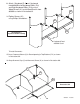
Back Panel #89830 Carrel 14.Attach Middle Side Panel (P-1) to Top Panel and the Middle Leg (P-5) to the Back Panel of #89830 Carrel as shown in illustration # 5. C D C 15.Secure by turning the Cam Locks (C) 1/4 turn until they lock. E P-5 Top Panel #89830 Carrel To Secure Cam Locks, Insert Large Phillips Head Screwdriver and turn Cam Lock 1/4 turn (90 degrees) clockwise. C P-1 Illustration # 5 16.
19.Attach Left Side Panel and Left Leg from #89830 Carrel to Top Panel (P-2) and Back Panel (P-3) as shown in illustration # 7. Illustration # 7 20.Secure by turning the Cam Locks (C) 1/4 turn until they lock. P-3 C C D Left Leg #89830 Carrel P-1 E P-2 21.Attach 2 Ganging Brackets (P-8) to the 2 Back Panels using 4 Screws (A1) and 4 Washers (B1) as shown in illustration # 8. Left Side Panel #89830 Carrel 22.Secure by turning the Cam Locks (C) 1/4 turn until they lock.
23. Attach 1 Keyboard (P-4) and 1 keyboard from #89830 to Left Keyboard Slides (P-8) and Right Keyboard Slides (P-9) using 4 Wood Screws (A1) and 4 Wood Screws from #89830 as shown in illustration# 9. A1 24.Tighten Screws (A1) using Phillips Screwdriver. A1 P-4 Illustration # 9 Keyboard Slide Assembly Keyboard Panel #89830 Carrel To install Grommets: 25.Insert Grommet Sleeve (H) in Round opening in Top Platform (P-2) as shown in illustration #10. 26.