
Operation Manual


Cable connections
>> Set up BeoVision 4
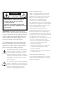
IR receiver: The screen has a built-in IR receiver. It
is therefore not necessary to mount a separat IR
receiver, as it is described in the BeoSystem
Reference book. Only if a projector screen covers
the built-in IR receiver when in use, you must
mount a second IR receiver and connect it to the
second IR-IN socket on your system.
Make the connections while both the screen
and your BeoSystem are disconnected from
the mains.
Connect the screen using the appropriate type
of cables. Refer to the illustration here – and
to the Reference book for your BeoSystem.
If in doubt, contact your Bang & Olufsen
retailer.
When all connections are made, connect your
whole system to the mains supply. The screen
(and the BeoSystem) can only be switched off
completely by disconnecting it from the mains
supply. However, the screen is designed to be
left in standby mode – ready for use.
It is necessary to secure the mains lead in the
cable bands. Otherwise, the mains cable can be
tugged free of the socket.
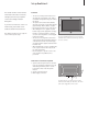
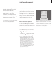
Sockets on the connection panel
The connection panels on the back of the screen
contain the sockets for connection to the
BeoSystem – and connection to the mains supply.
The socket marked PC IN (covered by a small lid) is
not to be used in a setup with a Bang & Olufsen
system!
SLOT 2 (DVI-connection)
Socket for connection to the socket marked
DISPLAY 1 on the BeoSystem.
SLOT 3 (IR-connection)
Socket for connection to the socket marked IR IN
(9-pin) on the BeoSystem.
SERIAL
Socket for connection to the socket marked
MONITOR on the BeoSystem.
SLOT 1 SLOT 2
DVI-D IR
SLOT 3 PC IN SERIAL
SERIAL DVI
(SLOT 2)
IR
(SLOT 3)
MONITOR
DISPLAY 1
IR IN
(9-pin)
BEOSYSTEM 3
4