BeoLink Gateway Type 1703 Installation Guide Ver. 1.
Contents Page BeoLink Gateway BeoLink Gateway vs Master Link Gateway Features Sockett panel Technical specifications Basic functionality Master Link setup Network Link setup Network Link / Master Link setup Supported Home Automation Systems BeoLink Gateway compatible products LED System Status / Setup Button Web-based User Interface Connecting a PC to BeoLink Gateway 1 2 3-4 5 6 7 8 9 10 11 12 13 14 15 Menus: - Start Menu - Login - Project - Setup - Network Settings - Date & Time Settings - Integration
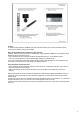
BeoLink Gateway BeoLink Gateway is the successor to Master Link Gateway and is a control interface between Bang & Olufsen products in a BeoLink system (Network Link/Master Link) and one or more Home Automation Systems. BeoLink Gateway has a Web-based User Interface and can be accessed via the Internet browser on a computer - Google Chrome or a similar browser.
BeoLink Gateway versus Master Link Gateway: Main differences between Master Link Gateway MKII and BeoLink Gateway: - New programming web interface - More opportunities and flexibility in the programming interface. - General rules can now be added. - Macros does not have to be built from scratch for each zone. - Wait times can be added for each command in a macro. - Use of astronomic clock for timer events. - Possible to add own drivers in the future (“Lua” scripting language). - Independent of SW releases.
Features Web panel. Connection of IP-cameras. Home Automation menu on the TV - Like Smart TV. - Overview/status/control of the entire house. - Two-way feedback form Home Automation systems. - Set-up and control of IP cameras. - Must be setup manually in the browser in the TV using the IP-address of BeoLink Gateway. Network Link functionality - Control and status from Network Link products. - PUC control received automatically from the TV’s. - Favourite logos for TV and Radio stations to be programmed.
Features In a BeoLink setup (Network Link/Master Link) with a BeoLink Gateway and a Home Automation System connected the following features are available: Beo4, Beo6, BeoRemote One and BeoLink App operation Operation of Bang & Olufsen products in a BeoLink Link system (Network Link/Master Link) with Beo4, Beo6, BeoRemote One and the BeoLink App. - Home Automation System operation with Beo4, Beo6, BeoRemote One - via the BeoLink system from every zone (product) in the house.
Socket panel Mains For the connection to the mains. Network Link (Ethernet) For the connection to a Network Link router to have communication via Ethernet with a IP-based Home Automation system and the Network Link. USB The USB sockets are for the connection of Home Automation systems with RS232 and RS 485 communication. This requires an USB ↔ RS232 converter. The USB ↔ RS232 converter for the B&O ServiceTool can be used.
Technical specifications Type no: - Type 1703 - One type only. Mains - 100 V~ - 240 V~ - 50 Hz/60Hz. Power consumption - 7.7 W - 13 W - with USB devices connected. Display - Internal Web server. Operating conditions - Temperature: 10° C - +50° C. - Humidity: 20% - 80%.
Basic funtionality Control flow The control flow in BeoLink Gateway is based on macros by their functionality. A macro contains a list of ‘EVENTS’ (data) and a list of ‘COMMANDS’ (data). A macro is triggered (activated) by an ‘EVENT’, which could be an IR command from a B&O remote control or a command from the Home Automation System. The ‘EVENTS’ from the products on the Network Link and/or the Master Link and ‘EVENTS’ from the Home Automation System are ‘mapped’ (listed) in BeoLink Gateway.
Link. - Receives (Rx) status information from products on the Network Link and the Master Link. Status is passed on by the BLGW protocol to the Home Automation System via Ethernet or USB/RS232.
Master Link setup ISP router The ISP (Internet Service Provider) router gives access to the Internet and is used as router for computers on the LAN and for the BeoLink Gateway. BeoVision 7-40 BeoVision 7-40 is the ‘video master’ in the Master Link setup and is set to option 2. The TV is connected in the Master Link system with a Master Link cable from the Master Link socket to a junction box. - Rerouting The re-routing of light and controls commands to BeoLink Gateway must be enabled in BeoVision 7-40.
the BeoLink Gateway. - MLGW Status: Must be enabled only if the Home Automation System connected is equipped with a display. Enabling MLGW Status allows display information to be shown in the display on the Home Automation System panel. - BeoLab 3500 BeoLab 3500 is in option 6 and connected in the Master Link system via a Master Link cable from the Master Link socket to a junction box.
Network Link setup ISP router The ISP (Internet Service Provider) router gives the BeoLink Gateway access to the Internet and is used as router for computers on the local LAN. Router and switch As most ISP routers have a stable connection to the Internet and to products connected on the LAN it is sufficient to build a Network Link setup based on the ISP router. As more LAN connections are needed a switch can be applied. - Switch The switch is connected to a LAN port on the ISP router.
Network Link to the B&O products and/or via the Ethernet/RS232 to the Home Automation System. (See Basic functionality).
Network Link/Master Link setup ISP router The ISP (Internet Service Provider) router gives the BeoLink Gateway access to the Internet and is used as router for computers on the local LAN. Router and switch As most ISP routers have a stable connection to the Internet and to products connected on the LAN it is sufficient to build a Network Link setup based on the ISP router. As more LAN connections are needed a switch can be applied. - Switch The switch is connected to a LAN port on the ISP router.
Service Menu’ [Settings]. The hostname for the BeoLink Gateway must be entered, for instance ‘BLGW’. NL/ML Delay Box A delay box is mounted in the Master Link system to prevent echo-effects (delay) between the Network Link product and the Master Link products in Link Room. The delay occur because the audio signals are converted from analog signals on the Master Link to digital signals on the Network Link.
Supported Home Automation Systems Lauritz Knudsen, IHC-Schneider, LexControl KNX - EIB Clipsal Legrand - Bticino SmartHouse Lutron - Lutron HomeWorks Interactive - Lutron Homeworks QS - Radio Ra2 - Grafik QS - Lutron Graphic Eye - Lutron Radio Ra Vantage Dynalite Conson XP Custom Strings Velux 11
BeoLink Gateway compatible products - ML products - BeoVision 7-32 MK I - MK IV - BeoVision 7-32 MK I - MK IV - BeoVision 7-32 MK V - BeoVision 7-40 MK I / MK II - BeoVision 7-40 MK I / MK II - BeoVision 7-40 MK III - BeoVision 7-40 MK IV - BeoVision 7-40 MK V - BeoVison 7-55 - BeoVison 7-55 MK II - BeoVision 8-26/32 - BeoVision 8-40 - BeoVision 8-40 MK II - BeoVision 9-50 MK I - MK III - BeoVison 10-32/40/46 - BeoSystem 3 / MK II - Beosystem 3 MK III Software ≥ SW 7.94 ≥ SW 30.08 ≥ SW 10.11 ≥ SW 7.
*As the audio products are ML audio masters they can be used alone with BeoLink Gateway. All Audio Masters are able to receive commands from BLGW, no matter which option they are in. In a integrated setup (option 0) the commands must be send to the Video Master using the audio master as source center. Note! For further information about SW versions and compatibility follow the link: https://retail.bang-olufsen.dk/beowise/BeoWise_UK.nsf/DocName/Tip.MLGateway.17981799.
LED System Status BeoLink Gateway is equipped with an LED indicator, which is used to display the system status of BeoLink Gateway. The LED, placed at the lower part of the connection panel, is also used to give feedback when the Setup button is operated.
Web-based User Interface BeoLink Gateway contains a web-based User Interface - as in a router. This means that the user interface can be accessed by using the Internet browser on the PC. All configuration of BeoLink Gateway is done by means of the web-based User Interface. The browser must be, for instance Google Chrome, IE 10, Safari with Bonjour or a similar browser. Navigation The User Interface contains different menus, which can be selected in a navigation bar.
Connecting a PC to BeoLink Gateway Basic connections As the BeoLink Gateway contains a web-based user interface a PC must be connected to be able to access the user interface. The user interface is used to setup and configure BeoLink Gateway. The PC and BeoLink Gateway can be connected in two ways: - BeoLink Gateway connected to a LAN. If a router is available it is recommended to connect the BeoLink Gateway and the PC via the router.
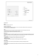
Start Menu Access to the menus The WEB-based user interface can be accessed by using the Internet browser on a computer. The latest browser’s are supported. Bang & Olufsen recommends Google Chrome. As the DHCP is enabled by default the IP-address - allocated by the router - must be typed in the address field of the browser. If DHCP is disabled the default IP-address - 192.168.1.10 - must be typed in the address field of the browser.
Login Login To access the configuration and programming menus ‘admin’ must be entered in both fields in the login box followed by . The ‘Password’ can be changed, while the ‘User Name’ is always ‘admin’.
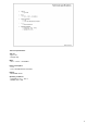
Project Menu Bar All menus in BeoLink Gateway can be accessed via the menu bar in the top of the display. The following menus are available: - Project - Setup - Zones - Systems - Resources - Macros - Interfaces - Configuration Project Menu The Project Menu can be used to give information concerning the project. It is possible to store the following information: - Project name - Any name, number, etc. - Display name - The display name will be shown on all user interfaces, BeoLink App, WEB panel, etc.
Setup - Network settings The Network Settings menu is used to setup the network settings to adapt to the actual network to which the BeoLink Gateway is connected. BeoLink Gateway is delivered with DHCP enabled from the factory, which means that the network settings are assigned automatically. All the network settings can be changed in the Network Settings menu. Hostname The name by which BeoLink Gateway is found in the LAN.
Setup - Date & Time Settings Date & time settings A correct time setting is important as it is used for the monitoring of events, astronomic clock events and for time stamping the error log, for instance to show the exact time a fault has occurred. The system will still work even if the time setting is not correct. The date and time settings can be synchronized with Internet time servers (recommended) if BeoLink Gateway has access to the Internet or they can be set manually.
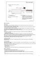
Setup - Integration Protocol Settings Integration Protocol The Integration Protocol makes it possible for other devices to interact with BeoLink Gateway. The protocol is used by mobile applications or by other home automation controllers. Integration protocol can be enabled on the local network, as well as on the RS232 port. Note! To be able to use the BeoLink App the Integration Protocol must be enabled on the local network. TCP port For the LAN a TCP port must be allocated. The default port is 9000.
Zones Zone Settings Name In BeoLink Gateway rooms in the house, such as living room, kitchen, bedroom are organized in zones. Area Zones are organized in areas to be able to handle big installations. An area could be: ‘Guest house’, ‘Basement’, etc. - ‘Global’ ‘Global’ is a special zone and it has its own special area. It is meant to be used for resources that apply to the entire house.
Systems The systems settings is for setting-up systems connected to BeoLink Gateway. BeoLink and Home Automation systems are ‘systems’. System settings Select ‘+’ to add a new system. Any of the supported systems can be added, except internal systems, which only appear once in the installation, such as BeoLink and Virtual Resources. BeoLink and Virtual Resources are added by default. It is possible to change zone, rename the system, and to adjust the configuration and connections settings of the system.
24
Resources - BeoLink resources The components in a system is mapped to a resource. The resources have the following parameters: - Zone The zone to which the resource belongs. Is used for setting-up BeoLink Gateway and for the generation of user interfaces. - Name For easy identification the resources should be named. -Type The type of available resources depends on the actual system, for instance a button, a dimmer or an A/V product. - Address Unique identification of a resource - the serial number.
Resources - Home Automation System resources Standard resource types Most resources from the supported systems fall into a few groups: buttons, dimmers, shades, etc. BeoLink Gateway defines a set of standard resources with a basic functionality, for example: - a standard button supports PRESS, HOLD and RELEASE actions plus a status indication (a LED that can be ON or OFF). Some systems can extend the standard button to provide extra features.
Resources - Virtual resources Virtual Resources Virtual Resources makes it possible to define buttons for systems, without implementing these directly. The BeoLink App currently uses virtual buttons for displaying scene buttons. It is not able to display all available resources in each zone. Virtual Resources have no functionality by themselves. Macros must be defined to link user actions on a virtual resource, with events and commands on the systems.
Macros Macro Programming The interaction between the devices connected to BeoLink Gateway is defined by means of macros. A macro consists of a set of events and a list of commands. When any of the events which are defined in a macro occur (e.g. a key press on a keypad, a Control Command on Beo5), the macro will be triggered. This means that the commands in the macro will be executed in order. Macros are also assigned to zones, even if they do not correspond to physical device.
Macros - Resource Event Defining Events The list of events - for triggering a macro - can be filled in manually, or selected from recent events. Three types of events: - Resource events Resource events match a specific event on a specific resource. - System events System events include calendar and astronomical clock events and system connectivity events - Generic events Generic events apply to a number similar events throughout the house.
Macros - Resource Command Commands Commands are the actions executed when a macro is triggered. The list of commands is executed in order, and a delay can be set before each command as a combination of seconds and milliseconds. The list can be reordered by dragging the handles at the left of each row, or by clicking on the arrows on the far right of each row.
occur. The possibility to cancel or collapse a macro being executed ensures that the ongoing macro will end immediately. In the above mentioned example, the macro to switch the home theater off should first cancel the macro for setting-up the home theater: THEATER OFF macro commands: - 1. Cancel THEATER ON macro. - 2. Raise screen. - 3. Shut down projector. - 4. Switch BeoVision to STAND-BY. - 5. etc.
Macro - Generic Resource Event Generic programming Standard events and commands apply to a single specific resource. Generic programming makes it possible to refer to a whole set of resources at once. It is possible to specify: - A single command to mute all products called BeoVision. - An event specification that matches any button pressed that is called Light On.
Macro - Generic Resource Command 32
Interfaces This menu is for setting up the user interfaces generated by BeoLink Gateway. It is possible to configure the following features: - Virtual resources, which provide a friendly way for interacting with some systems. - Sources and features of A/V products. - Lists with favorite TV channels and radio stations. - IP cameras access in the house. - Users which can access the system and restrictions.
Sources For each product sources available to the user can be added. For Network Link products it can be queried directly from the product by pressing the Synchronize sources with product button. The information to provide for each source is the following: - Source: Actual IR command for selecting the source. - Name: Optional label to show with the source. Max. 5 to 6 characters. It is recommended to leave this field empty unless a specific description for this source is required.
configuration section for each source. For each favourite list a global delay and end command - that will affect each favourite command - can be set. The end command must be added at the end of each favourite command sequence and can be either PLAY or SELECT. The global delay is added between all digits and between digits and the end command for each favourite command. For listed TV channels/stations the following information should be provided: - Caption: A short description for the favourite.
Tools To access the Tool menus select ‘Tools’ in the menu bar. A drop-down box with the sub-menus will appear, and any of the sub-menus can be accessed. Monitor The ‘Monitor Menu’ shows a list of the 100 latest actions which have occurred - events, macros and commands. The menu can be used for the following: - To find the precise addressing of a specific component. If a keypad, a sensor, etc. is activated on the Home Automation System, the event generated will be monitored by the tool.
Tools Logs The ‘System Log Menu’ is able to show system messages concerning the interaction between BeoLink Gateway and external devices connected, such as application errors and critical system errors. The menu can be used to: - verify the connection to external devices. Errors will be shown. - check of incoming ML-Gateway protocol connections. The size of the system log is limited, which means that old messages will be deleted when new messages appear.
Tools Service Reports If a hardware or software error is experienced it is possible to create a service report by pressing the ‘Download Service Report’ button. The service report contains information concerning the current configuration, BLGW identification and the recent activity. To download the service report on a connected computer, press the ‘Download Service Report’ button. The contents in the text-box must be copied into to an e-mail and the service report should be attached to the e-mail.
Tools Firmware This menu is for updating software. There are two ways to update software - manually via computer and on-line updating via the Internet.
Configuration - Save Revision Save Revision Saving a revision means saving the current configuration. The revision can be named, which is useful if changes have been made to the configuration. The saved revision is available in the Revision History list and can be restored. Versioning and backup Every time changes are made - in any of the configuration menus - during the setup of the system changes takes effect immediately - this is the ‘current configuration’.
Configuration - Load from file Uploading a configuration from a computer By selecting ’Configuration’ -> ‘Load from file’ a configuration file can be uploaded into BeoLink Gateway. The uploaded configuration will become active immediately and substitute the current configuration.
Configuration - Download To File Saving a revision to a computer By selecting ’Configuration’ --> ‘Download to file’ the current configuration can be downloaded to a computer. It is recommended to take a copy of the configuration when leaving an installation. it can be useful to a have as a reference if a problem should occur or as a back-up if the BeoLink Gateway should be defective.
Configuration - Revision History Revision history BeoLink Gateway keeps a record of the latest ten configuration releases. A new release can be saved by selecting ’Configuration’ -> ‘Save revision’. Every time a configuration is saved the system prompts for a short description of the revision. The current configuration is copied to the top of the revision history. If the revision history contains ten revisions, the oldest revision is discarded to leave space for the latest revision.